| Allplan
FT
user pages Smart Symbol Designer... a few suggestions Back to Allplan Users Main Page |
|
| Introduction |
|
Smart
Symbol Designer
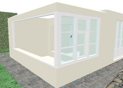
The project is to create a window frame around a corner which contains fixed lights and some sliding sash type opening lights - the opening sashes are unequal 1/3 upper and 2/3 lower rather than the usual equal sashes.

The project is to create a window frame around a corner which contains fixed lights and some sliding sash type opening lights - the opening sashes are unequal 1/3 upper and 2/3 lower rather than the usual equal sashes.
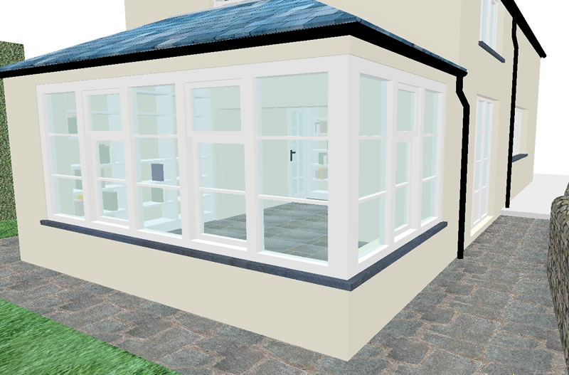 |
Here
(left) is the finished window. I find it simplest to create the corner window opening (v2003) first and then in another drawing file to create a new wall at the same bottom and top level as the window opening to form the outer frame of the window frame assembly - see the sequence below... |
|
(click
for larger version) |
||
Setup...
 |
<
.. make a corner window... General Note: I always point at the outer face of a wall when creating a new window opening - this affects the 'inside' and 'outside' settings within the Smart Symbol Designer ... |
|
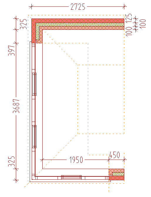 |
<
.. plan dimensions for reference... In this setup, the wall bottom levels are -320 mm the window bottoms levels are 600 mm the window head levels are 2150 mm the wall tops are controlled by a roofplane with an offset of -25 mm to the line of the plane... the roofplane values are Angle - 26.343 degrees Eaves - 2350 mm Top Level - 3072 mm and the plan offset of the roofplane outline is 100 mm round 3 sides of the plan |
|
(click
plan for larger version) |
||
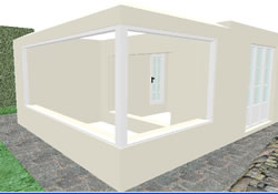 |
<
.. in a new drawing file create a wall 100 mm thick to same top
and bottom level as the earlier opening so as to run within it on
the line of the proposed window frame - putting
these in a new file stops Allplan objecting to creating walls on
top of walls now make new window openings also in that wall leaving 50 mm say, at the ends and 100 mm 'post' at corner.... this creates an outer 'frame' while also giving the openings and reveals needed for the Smart Symbol Deisgner to work... |
|
 |
I
have the frame thickness set to 100 mm in the window opening Reveal
settings, to match the 100 mm thick 'wall' acting as the outer frame
- outer Reveal is '0' and Inner
reveal is '100' assuming that when you created the window
openings you point first to the outside face of the wall. < .. here one side has been filled using the Smart Symbol Designer - details as follows for the larger opening... |
|
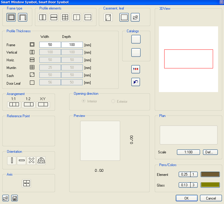 |
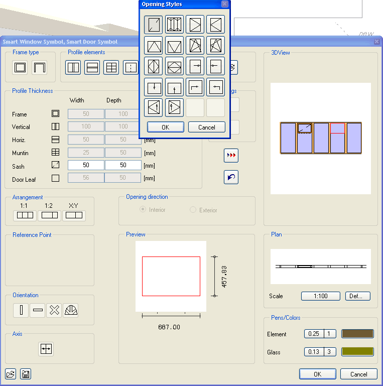
<
.. < .. this dialog should appear I have made a basic outer frame 100 x 50 mm ... (I assume you know that the chevron button applies elements once set up and the black anti-clockwise arrow removes elements in the order created) |
|
(click
for larger version) |
||
 |
< ... and have chosen to divide the remaining space into 5 equal
panes using 100 x 100 vertical elements - you can see the preview
in the lower part of the dialog... |
|
(click
for larger version) |
||
 |
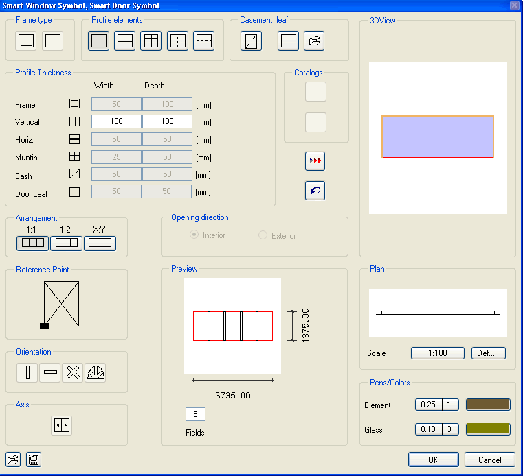
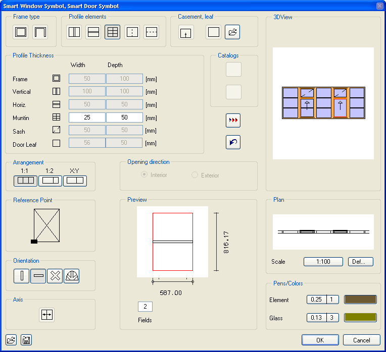
<
.. the trick now is to divide the window panes without adding any
new members yet... for this you use the icon furthest right in 'Profile Elements' section at the top of the dialog - it shows a horizontal dashed line... However, you also need to engage the 'Arrangement' icon called '1:2' in the middle left of the dialog... and enter the values '2' and '1' as shown below the preview in the dialog... this allows the top section of the sash windows to be 1/3rd of the total pane height... (the fixed lights do not need this treatment)... |
|
(click
for larger version) |
||
 |
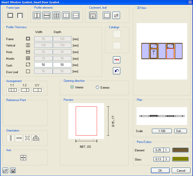
<
.. I am going to have 2 opening sash windows and so have divided
2 of the panes as described above... now, click on one of these new areas at the top and it will edge red to show it is selected, then click on the leftmost button in the 'Casement, leaf' area (top middle right of dialog).. the top left 'Opening Styles' option is the only one I know of which puts the sash/casement in the MIDDLE of the frame - all the others seem to stick out at the front or back. You will notice that 'Opening Direction' is greyed out for this sash type. Repeat for both top sashes (One is shown completed in the image, left). |
|
(click
for larger version) |
||
 |
<
.. repeat this process but selecting the lower part of the sash
windows and choose from the 'Casement, leaf'
button (don't be put off by the button
appearing to stay down! press it again..) this time
choose the sash/casement with the 'up' arrow on it... Notice that 'Opening Direction' in the middle of the dialog is active and you can set where in the frame - front or back - this sash/casement element is positioned... set it to 'Interior' to simulate the offset in a real sash window of this type - OK if viewed from the exterior of the building but not so good from the inside as it comes beyond the line of the frame... although some fiddling around with the wall and reveals when first set up might get around this? |
|
(click
for larger version) |
||
 |
<
.. lastly (as Allplan will not let you do much further after you
have set these elements) set up the smaller glazing bars... Click the one of the fixed panes to highlight it and then click the middle button in 'Profile Elements' (top of dialog) - I have these 'Muntins' set at 25 mm x 50 mm 'Arrangement' option is set to 1:1 'Orientation' option is set to horizontal.. 'Ratio' option is set to '3' iApply to the fixed lights and then.. |
|
(click
for larger version) |
||
 |
<
.. repeat
for the lower sashes but set the 'Ratio'
to '2' Save the assembly using the icon at the bottom left of the dialog or after you click OK and apply the symbol. Notice that it is useful to have an elevation or isometric view of the location of the window active when inserting as the assembly will not display in the OpenGL animation window until you have confirmed the insertion by right-clicking in the workspace - whereas it does show up in the ordinary viewports (you cannot tell just looking in plan whether the sashes are offset the right way round). |
|
(click
for larger version) |
||
With some trial and error you can make most straight framed doors and windows within the Smart Symbol Designer. Free form openings can also be framed.
[to be continued]
+
+ +
Please
email any
comments or corrections
Return
to Allplan FT Users Main Page