Allplan FT 3D techniques page [revised 07.02.02]

Bay window, slated roof, glazed frame construction - this is a common form of construction for bay windows and initially seems tricky to model in 3D. The key is to separate out architectural elements that might interact. Thus the low walls at the base are in one file, the glazed frame - which is a wall with windows created right up to the angles is in another drawing file and the roof and any infill walling above the frame and the roof construction is in another.

Based on project displayed on works 7 page....


If anti-aliasing is turned on during raytracing in Allplan the junctions of elements that are in the same plane but overlap will show up - in this image the junction of the bay roof and the main roof for example.

 
this other bay proved a slight problem because the eaves line did not follow the shape of the bay - requiring a few extra construction lines to create the roof outline in plan

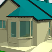
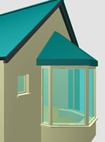
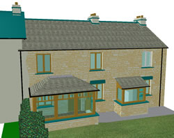
The cills are 3D solids (they do not interact with arch elements in the same drawing file). A tricky problem turned out to be how to set up the roof planes to make this type of roof.
Based on project displayed on works 7 page....


to align the short width pitch roof on the right hand side here to exactly match the main roof slope set up a normal pitch roof plane initially and copy the attributes from the main roof using the double chevron button in the roof modeller dynamic tool - apply the slope then do the same for the other side...[Update - since doing the overlapping roof - also in the 3D techniques section - I think a better method would be to use a similar technique for this roof as shown for the overlapping roofs - and do all the slopes by the 'roof by 2 points' method]

 
a problem is visible here - the planes do not meet in the correct place - all lines should meet at the left end of the small piece of ridge but for some reason they would not meet - in the end I left it like this with a small twist in the roof - not worth the time and effort to get it absolutely straight - the client might not like it anyway!
...but then for the remaining sides change to the roof by two points method ensuring that you keep the eaves height the same as the pitches already made and get the ridge height with the measure tool as the top point and the eaves as the bottom point - there are probably other ways to do this also

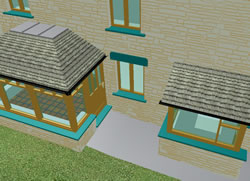
Update Feb 2002
recently I had the problem of how to make a flat topped roof to a porch...
Based on project displayed on works 10 page.... (in preparation)

 
I actually did it by make a roof plane for the upper part of the porch in a separate drawing file, putting a free form wall controlled top and bottom by planes within the roof plane and setting a height limitation (that triangle symbol with the top cut off in height setup), converting the wall to a 3D object and then converted it to planes to replace the original planes and thus control the roof structure and coverings..
UK tech support pointed out that I did not need to do this.. just set the 'top' height of the roofplane to the level you want to have a level area - it normally defaults to 10 metres...
D'oh!
.......... :-)


back to 3D techniques page