Allplan FT 3D techniques page [rev 23.09.02]

Overlapping roofs - I have one of these on a project at the moment and so a recent request for suggestions on how to tackle the problem was timely... here is my suggestion for how to set about creating overlapping roofs on different storeys...
The finished effect - fairly common roof arrangement in vernacular architecture....


this is the effect we are trying to achieve

 
we want to overlap rafters and roof coverings

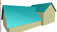
Draw the single storey part in one file, the adjacent lower storey in another and the upper floor adjacent in another file - this prevents unwanted interaction of any roof plane overlaps - we want overlapping roof planes so that the rafters can oversail the gable walls of the buildings if necessary. Rafters can not be automatically inserted beyond the end of the roof plane (as far as I know - rafter 'feet' can be extended or cut back)
1. Setup of the 3 rooms -use the default settings of wall tops to align to upper plane


there would normally be a storey below these but it is omitted to concentrate on the roofs only - each room in a different file - default planes at 0 and 2500 and for top storey set to 2500 and 5000 (units are mm)...

 
apply the roof planes to the lower part... there is an offset of 250 mm to the roofplane round 3 sides of the lower storey and 0 offset on the side against the 2 storey part...

make sure that the roof planes are inserted in the same drawing file as the appropriate room so that once completed the walls adapt to the roof shape automatically
2. Complete initial roofplanes setup and switch to 3 windows view if not already on ...


the same offset is applied to the roofplane applied to the upper storey but to all sides this time giving a 250 mm overhang all round...

 
switch to the 3 windows screen setup so that you can see the elevation, isometric and plan all at the same time - switch to the end elevation - here is the left view...

the first time I did this roof I 'cheated' a bit and used a 2d wireframe of the elevation rotated and lined up with the plan view to check the position of the intersections of roof planes and then added construction lines to snap to later however there is no need - this is a simpler and more elegant solution using the 'elevation line' property of roof planes...
3. Use the measure tool to apply roofplane intersection heights to 'Elv Ln' parameter...


in plan you can see the roof planes - the faint orange lines are the elevation lines which are not set to any particular value at present... the trick is to right-click on the lower roof plane which brings up 'roof frame' shortcuts menu and then click on 'properties' which brings up the 'modify roof frame' dialogue... click on 'Elv Ln' so that the existing entry becomes highlighted... now click on the 'measure' tool, choose 'coordinates' and then activate the left elevation window by clicking on it's title bar...in the elevation window click on the intersection of the lower roof plane and the upper roof plane - as in the image (right)

 
- the measure tool will give you an x, y and z value... click on the 'z' value and it should be automatically transferred to the 'Elv Ln' property which in turn immediately updates the plan position of the elevation lines... either intersection will do - you do not need both points - note that although it is an intersection the cursor tip shows an endpoint snap indicator
update 23.09.02 intersection markers now fixed
... this technique also works with asymmetric roofs since the intersection with the upper roof plane is at the same level in all cases... 'Esc' out of all tools..

We are setting up the elevation lines within the roof planes so that when we create the dormer to the upper storey roof plane there will be points to snap to in plan view
4. Apply the ridge height of the lower roof to 'Elv Ln' parameter of the upper roof plane...


- Right-click on the upper storey roof plane and as before get the 'modify roof frame' dialogue up and click in the 'Elv Ln' box to highlight the current value - click on 'measure' which should still be have 'coordinates' highlighted, click on the green tick button to accept - activate the left elevation window by clicking on the window title bar (you can probably skip this with practice) and click on the apex of the lower roof plane


- this will bring up the measure tool result box and once again click on the 'z' value to have it automatically transferred to the 'Elv Ln' value in the 'modify roof plane' dialogue - if this doesn't work it will be because the 'Elv Ln' entry was not left highlighted before activating the 'measure' tool... 'Esc' out of the tools and the result should be as shown above...

This approach allows rafters and valley beams to be correctly created in upper and lower roof planes - if you try to do this all in one plane you will not be able easily to create rafters in the lower roof plane which run under the upper roof plane overhang - it also minimises the chance of problems with roofcoverings later on... roof coverings are prone to doing strange things where they are extended beyond the actual roof plane outline...
5. Create a dormer in the upper roof plane which matches the slopes of the lower plane


Make the upper roof plane drawing file active, click on the 'dormer' tool in the 'roof modeller'. The pink line is the outline of the dormer created in plan view - the top left corner of the outline is a left-click point snap but the bottom right corner has to be clicked using the 'linear snap' method with the middle mouse button - turn off 'element snap' in the point assistant for this to work - obviously 'linear snap' has to be turned on - note that 'gable/hip roof using 2 points' button is selected in the 'modify roof frame' dialogue...


to complete the dormer click on point 1 and point 2 in the left elevation window - the same 2 points earlier selected for setting up the elevation lines (planes intersection and ridge height of lower plane) - and apply the slope to the relevant side - do the same for the other side and 'Esc' out of the tool... the result should be as shown above. I have left the overhang to the dormer overlapping with the lower roof plane - it should not cause a problem - you just have to set the region for rafters to the dormer later to less than the full depth of the dormer...

There may be other ways to do it but I find this approach logical and tidy - it also illustrates the modelling power of Allplan and how to integrate the measure tool as an 'interrupt' with active tools
6. the completed roof planes and with rafters...


isometric view of the completed roof planes and walls aligned to them...

 
simple scheme of rafters applied - some 'locking' and adjusting of the rafter positions is usually necessary around the overlap...

A reminder of the finished effect....


with roofcoverings - no ridge tiles - incidentally for ridge tiles I normally copy the roof planes to another drawing file and then create a narrow strip of roofcovering to the thickness and position of the ridge tiles within that file

 
to shorten some rafters and not others just 'lock' a rafter at the end of a region which then divides the rafter region into discrete areas which can have different properties set - there is a button to step through the regions in the properties dialogue for rafter design...

Much quicker to build than explain - any suggestions, comments or queries - please


back to 3D techniques page