 Eyebrow dormer - this uses a technique common to most complex modelling
tasks in Allplan - build a 3D solid and then convert it to reference planes.
Eyebrow dormer - this uses a technique common to most complex modelling
tasks in Allplan - build a 3D solid and then convert it to reference planes.
Update 18.09.01 - following
a request for a more detailed explanation I attach the reply (based on the
'Step-by-Step' guide 'Advanced 3D Modelling') at the
end:
| Based
on project displayed on works 4 page.... |
|
draw
it in 2D and then convert to 3D elements and rotate front face
|
|
convert combined solids to planes |
The trick with
the eyebrow is to draw it in 2D elevation first if you want one with a sloping
top (if a horizontal top to the curve is OK then just use the dormer tool
with barrel roof option in the roof modelling module) - make an outline
of the front face and then the slope in elevation, convert both to 3D elements,
move the front face outline so that the top is attached to the bottom of
the slope line, rotate the front face 90 deg on a vertical axis and then
use 'polyline sweep solid' to generate a solid of the dormer shape along
the slope line. The roof solid can be generated from the normal roof plane
filled with a free form wall and then converted into a 3D solid.
| Based
on project displayed on works 4 page.... |
|
planes
will work with rafters etc.
|
|
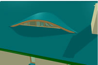
with the rest of the model and wall and window inserted - note fillet
of roof covering running up to cill... |
To place the
dormer in the correct position I refer to the 2D elevation and use parallel
offset construction lines (they offset into the screen direction from any
elevation view and are automatically created as 3D construction lines).
Rather than try for exact snapping try to ensure a small overlap of the
dormer and roof line - this should ensure that there are no 'overhangs'
between the front face of the dormer and the slope of the roof solid - while
it will not prevent a 'union' of the solids it will prevent them becoming
a reference plane. Use the 'union' command in the 3D modelling module to
join the solids and then in the 'architecture' module use '3D to planes'.
Note that this command prefers that you point at the solid rather than outline
it. You should now have a reference plane which you can use just the same
as a normal roof plane to create rafters and roofcoverings etc. Some ingenuity
is required to create an overhang of the roofcovering to the front face
of the dormer - I just recessed the wall/window running under it and made
a 3D 'fillet' of roofcovering to fill the gap between the bottom of the
frame and the roofslope. The wall and window head will take up the shape
of the dormer if the window/wall top is associated with the upper plane
and the smart symbol designer will also work as normal with any opening
in the wall.
Update
Reply 18.09.01 to emailed request for more detailed information on how to
make this work. The page references are to the 'Step-by-Step' guide 'Advanced
3D Modelling' available from your Nemetschek Distributor
The
'hidden line image' method suggested in the SBS guide is just a suggestion
of a way to create the end profile of the building in 2D - I think
in fact I just drew it in 2D from scratch as it was a fairly simple
outline (but see later!).
The first important part is on page 83 of the SBS - you draw the end
elevation of the building which is also the side elevation of the
dormer in 2D - (note that this is only necessary if the dormer is
to have a sloped roof in side view - if it is level you can just use
the barrel dormer tool in the roof modeller instead) - you also need
to extend a couple of construction lines from the top and bottom of
the side view of the dormer to allow you to draw, again in 2D, the
front view of the dormer.
I experimented quite a bit with drawing the front of the dormer and
gave up using the 'spline' tool and just drew one half of the dormer
front view with a few straight lines which I then made curved using
the 'fillet' tool to click twice on the same line and bend it - when
I'd got the curve something like OK on one side of the centre line
of the dormer I reflected it to ensure perfect symmetry. Remember
to draw a horizontal line at the bottom joining the ends of the curves
to create an enclosed shape.
Once you have a drawing similar to the setup on page 83 you need to
convert the 2D lines of the dormer shape and ridge line (only) into
3D ones as described on page 84. Once they are 3D lines you move the
front view of the dormer into correct position on the roof slope -
as illustrated on page 84. You then need to '3D rotate' just the front
view of the dormer about the y axis so that it is now in the correct
relationship with the roof slope as shown on page 84.
You then need to rotate the dormer assembly of 3D lines 'up' off the
'floor' as it were by 3D rotating about the x axis - as shown on page
85. If you Delete all 2D lines in the drawing you should be left with
the front face of the dormer as a 3D line and a 3D line attached to
the top of the curve as per the illustration on page 85.
Now you can see why they suggested using a wireframe of the building
end elevation to make the 2D outline - the 3D lines will be correctly
positioned in relation to the actual 3D model (which has been in a
separate drawing file 'turned off' for the moment) - at least in elevation
if not in plan. If you just start off drawing it anywhere (as I did)
then some playing about in the various views is necessary to line
up the dormer correctly with the roof line.
In the SBS they seem to use the original building model (? not sure
- they would have had to move the 3D dormer and the building into
the same drawing file?) but I think I used a copy of the building
or also made the 2D outline of the building end elevation previously
described into 3D lines and extruded them to make a solid building
and roof at this point.
Once you have got the dormer 3D lines outline into the correct position
you sweep the front face back along the dormer ridge line as shown
on page 86.
Now before you use the 'union' command to join the solids into one
object it is critical to the eventual success of the whole operation
that you zoom right in - in end elevation view - to the junction of
the dormer solid with the roof slope - and check for any gaps. If
the dormer solid does not meet exactly with the roof slope solid (I
actually let it overlap with the roofslope solid fractionally just
to be sure) , no matter how tiny the gap, it will not prevent the
union of the solids but it will stop conversion to planes later on.
( A general rule of conversion of solids to planes is that 'overhangs'
anywhere in the solid prevent conversion to planes).
Assuming all goes well and you can convert the solid to planes it
is then just a question of how you work the plane in with your model
- I tend to use multiple copies of roof planes in separate drawing
files to prevent interaction of overhangs but if it was a simple building
then this plane just created could be used as is for the roof.
|
|