| Allplan
FT
user pages Smart Symbols ... a few basic tips Back to Allplan Users Main Page |
|||||||
| Introduction Smart Symbols are a great feature but not well explained to the new user. The online Help contains much, but not all, the information you need if new to Allplan. Nonetheless I have discovered that setting up smart symbols is really very easy. Allplan 2005 has improved on the features described below and the editing of symbols parameters is now very intuitive. Update September 2003 The new editing dialogs for smart symbols in v2003
|
|||||||
pre-version 2003 but general principles still apply for creating foils...
Before starting on creating symbols - a note about modifying existing smart symbols...
 There is a Smart Symbols module -
 but for some reason one tool does not appear in it...
For this you need to go to Tools on the main menu.
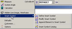
It is useful if you want to change pens or pen colours or fills of existing smart symbol 'foils'.
Note that the animation window cannot be open when you start this tool or an error message will appear.
'Foils' are the component parts of a smart symbol - each one is a drawing or model in itself and when defining the smart symbol you can choose whether each foil is visible in 2D and 3D or just 2D or just 3D and also at what scales they are displayed. The collection of foils is assembled into the complete smart symbol.
It will flash once but no other indicator appears.
However the tool is active and you can now use
ESC out of the tool and then ESC again will produce an alert box asking 'Save modified smart symbol in catalogue? Yes/No'.
Click Yes to update the smart symbol.
The many other tools in this module look interesting but I have yet to fully explore them.
Some relate to the attributes you can also attach to smart symbols.
Creating New Smart Symbols...
My intention here is to explain how I attached a 2D representation to an imported 3D object so that it looked 'normal' in plan - i.e. without all the extra lines a 'dumb' 3D object produces in plan - particularly a curved object. At the same time I wanted to attach surface colours to the 3D object to improve its appearance in the animation window and have the whole available as a smart symbol.
As a starting point I used one of Luca Dalla Benetta's excellent free models from his site at geometrica.it. (See page on importing symbols on some ways to import these)
 |
 basic model..... ..(left) view in animation window after colours applied.. isometric view... |
 |
 |
Here
is the plan view - both foils side by side just for convenience
- on the left a 2D outline of the 3D model obtained by a hidden
line export of the plan view of the
3D model. I cleaned up the odd spurious line and then added colour
fills matching those attached as surfaces to the 3D model. There
is no need to be this elaborate - a simple line drawing will do
- I just thought it worth the small extra effort to brighten up
the plan view! On the right is the default plan display of the 'dumb' 3D object (really a collection of 3D objects) as imported. You need to draw all your 'foils' in advance - view them in plan but keep the isometric window open also. |
When
doing the hidden line export set the option 'Remove adj. surface
edges' angle to around 20 to automatically remove many of the
lines produced by faceted faces. |
|
Start defining foils...
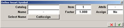 |
This dialog box (left) appears - click in one of the two empty boxes - 'Catalog' or 'Name'... | |
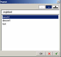 |
I
tend to click first in the 'Name'
box to give the symbol a name - results shown here (left)... and then in the 'Catalog' box results shown here (right) |
 |
to choose where to save it - but the order seems unimportant -
create a new folder in the catalog if you wish by right-clicking in the left window of the catalog dialog (shown here above far right).... |
||
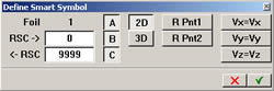
| Search on 'Define Smart Symbol' in the online Help index or press F1 in Allplan at this dialog | ||
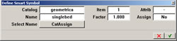 |
This is how the completed dialog box looks - if you want to know about the other entries - for the future - then the F1 online help in Allplan is quite good if a bit brief | |
| the command prompt says 'Define smart symbol foil 1' | ||
| Note that I have moved my command line prompt to the top of the Allplan window... | ||
 |
(left)
I dragged a selection box around the plan view of the symbol and
the lines highlighted in red - it is very small but you may be able to see that Allplan is now prompting 'click smart symbol's reference point'... (right) I then snapped to the top left corner... |
 |
|
Any point will do but it is very important that the same
reference point is used on all 'foils' - so pick one that is easy
to see in the plan view of both the 2D and 3D foils. I am just using 2 foils here but it is not unusual to have several foils - one for a representation at different scales - e.g. a detailed one for 1:20 and just an outline for 1:100 - you tie in the scale feature later on. |
||
| Click on 'Smart Symbol Display parameters' from the Help page indexed in Allplan as 'Define Smart Symbol' - or just press F1 at the following dialog box... | ||
 |
The
main dialog box now appears - notice that Allplan knows you have
just referenced a 2D symbol and so the 3D button is not selected
- there is 'bubble help' implemented on this dialog and so hovering
your pointer over the buttons will give an indication of what
they do. |
|
| Just
for this exercise I am leaving all the entries just as they are.
This means the same foil will appear at all scales - |
||
| Allplan now prompts you to define the next foil... | ||
 |
...
just as with the 2D symbol I dragged (left) a selection box around
the 3D elements in plan view and they all highlighted in red... and again you might see at the top that Allplan is prompting 'Click smart symbol's reference point'.. |
 |
| (above right) I have clicked the same reference point as for the 2D symbol earlier... top left of the bed | ||
 |
Now,
when the define smart symbol dialog (left) appears again click
on the '2D' button to unselect it.
This means that the 3D symbol will not appear in 2D view - i.e.
plan view. Instead the 2D symbol set up previously will display
in that view... Clever, isn't it? :) |
|
| Note that your foils once defined will disappear from view - they will reappear as part of the symbol once all foils are defined and you press ESC to exit the 'define foils' routine... | ||
 |
Press ESC when Allplan asks you to carry on defining more foils and this dialog box will appear. If you are going to change this - and I suggest you leave it alone for the present - then you need the isometric view enabled to see what you are doing | |
| press F1 in Allplan at this dialog for useful information for the future | ||
 |
Allplan seems to know what it is doing here and outlines the extents
of the 3D symbol - just to be on the safe side I usually click
E Pnt 1 and then click on the bottom
left corner of the construction line outline and then click on
E Pnt 2 and click on the top right
corner of same - note that you do not seem to have tool tips available
(the little cross beside the cursor) when selecting these points.
It may not be necessary - possibly the default values would do
- I have not checked yet. I usually leave Yes enabled in the dialog box - it permits the symbol to be resized. |
|
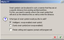 |
Almost there - now we are in routine territory - the 'smart
or dumb' dialog box appears asking if you want this symbol
to be intelligent or not. I chose yes... |
|
 |
The
symbol reappears and Allplan prompts for 'Click
reference line' - I clicked the back of the 'headboard'
of the bed - i.e. the top - |
|
| Using Symbols... | ||
 |
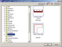
It has always puzzled me why you click on the 'Tagged Symbol' entry in the Right window to gain access to the user symbol folders - including the 'external path' folder. Thus the symbol just created above can be accessed by clicking 'Tagged Symbol'. |
|
| There might be a better way but I use Project Pilot to eventually transfer symbols created as described above into the Office symbols folder. | ||
There is an awful lot more you can do with smart symbols - linking them together, unlinking, modifying, replacing - and of course multiple inserts of a smart symbol are just 'instances' of the one symbol and so use up little memory or space.
[to be continued]
+
+ +
Please
email any
comments or corrections
Return
to Allplan FT Users Main Page