| William
Sutherland Architect |
|||
|
|
|||
![]()
Click
Here
to Return to
Allplan FT
Users Page 1
Office
Address Cluan
Rydal Road
Ambleside
LA22 9BA
015394 34489
For
location plan
see Local Links
|
|
User Pages for Allplan FT Some elementary rendering techniques...
|
Although appearing to trail behind the rendering feature list provided in packages like Revit and Microstation, Allplan is still remarkably effective at rendering models 'straight out of the box'. Here are a few things I have picked up while trying to improve my rendering skills that may help other novice users...
(once you master rendering from within Allplan you will almost certainly want to get to know the 'companion product' from Nemetschek subsidiary Maxon - Cinema 4D - which gives a more detailed level of control over lighting and textures, and with the Advanced Render module allows Radiosity rendering and since v9.5 also Ambient Occlusion - see using C4D and Allplan)
| Update
September 2003
- some minor changes since this page was
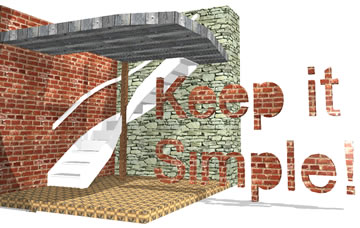
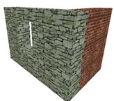
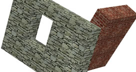
written for v16 - green check mark Update October 2004- some changes in v2004, although most of the text below still applies. v2004 added the ability to choose the surface for a wall in the Wall Properties setup. Still no fix for the problem of textures not rotating with the object. Update January 2006 - not a huge amount has changed in this part of Allplan over the years - some small improvements in lighting but I still use Cinema 4D for all my renderings. The image at the top of this page only took minutes to throw together (OK, so it looks like it... :) but it serves to demonstrate both the ease of use of Allplan for rendering and some of the issues that arise in practice... |
||||||||||||||||||||||||||||||||||||
|
Click
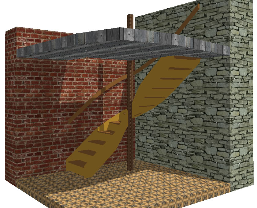
the image for a larger version and file size details... note that textures are applied to all sides of single layer 3D elements... |
 |
||||||||||||||||||||||||||||||||||
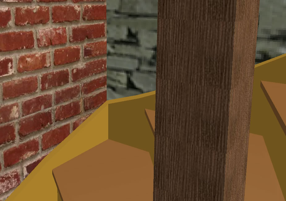
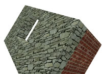
| The
brick wall texture is a higher resolution bitmap 'tile' than the stonework
- when you zoom in (right) the stonework looks 'fuzzy' because of
this. The stairs are in pen colours chosen to be similar to the desired
material and are always sharp but rather 'flat'. The post in the foreground
(right) has a reasonably high resolution timber texture. The floor
is a standard Nemetschek tile bitmap. All textures are applied using
a tool that has only recently been added to Allplan. |
||||||||||||||||||||||||||||||||||||
 |
Click
this ->
to get this...  Click in the space! |
 |
||||||||||||||||||||||||||||||||||
| Not
only does this allow you to select 3D objects in the manner of all
the 'Modify Format...' tools - i.e. select them all then confirm the
change by right-clicking in the workspace or clicking |
||||||||||||||||||||||||||||||||||||
 |
The buttons here are not self-explanatory - I highly recommend that you press 'F1' for the online context-sensitive Help and then the hyperlink 'parameters' from that Help window and then 'surface color and other parameters' once in the 'parameters' Help file. | |||||||||||||||||||||||||||||||||||
| Although I talk about 'textures' I really mean 'bitmaps that can be tiled in a seamless repeat' - Allplan stores bitmaps and property settings as a 'surface' file. Although it defaults to 'tif' format most common formats will work (jpg, tga...) | ||||||||||||||||||||||||||||||||||||
| This
dialogue can be summarised as follows: |
||||||||||||||||||||||||||||||||||||
 |
To understand all the options here (and some are duplicates of the last dialogue) you need to read the online Help file... however, pressing 'F1' alone is not enough here - you have to repeat the procedure outlined for the last dialogue box - i.e. click the hyperlink 'parameters' from the 'F1' Help window and then 'surface color and other parameters'. The most common parameters to change are the 'Scale' in X: and in Y: to make your bricks say, the right size on the model. | |||||||||||||||||||||||||||||||||||
| For glass you would want to change the 'Surface Properties' Transparency setting and Reflection. Most of the other settings are self explanatory because the finished effect is shown immediately on the cube in the Preview Window. | ||||||||||||||||||||||||||||||||||||
| 3.
Note that you can Save your settings here as an Allplan 'sfs' surface
file. 4. Note that if you click the blue 'undo' arrow or 'Off' check box you can re-import the bitmap via either of the two buttons in the 'Texture' section in the middle of the dialogue. 5. |
||||||||||||||||||||||||||||||||||||
 |
Click 'Yes' or your settings will be discarded! Once saved you will be returned to Allplan with your 'Surface' file name in the dynamic toolbar ready to choose 3D elements to apply it to - in the same manner as all 'Modify Format...' tools. |
|||||||||||||||||||||||||||||||||||
| Allplan
saves your 'surface' file for reuse. If you subsequently reload the
'surface' file and change any of the parameters then Allplan will
prompt you to save it again as above - a 'sfs' file is a combination
of bitmap and the parameters you have set for it's use in Allplan.
Thus you can import the same bitmap many times with different settings
which will all be saved as separate 'sfs' surface files in the
/nem/Allplan/STD/design folder on your 'data' drive (as defined
when you installed Allplan). Of course you can go straight to the 'sfs' files from the 'Surface' section at the top of the first level 'Custom Surface' dialogue if you have given them sufficiently descriptive filenames so that you know their properties.
|
||||||||||||||||||||||||||||||||||||
|
||||||||||||||||||||||||||||||||||||
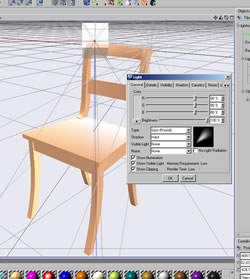
| Sun settings are on the left side of the dialogue:(click for larger version) | ||||||||||||||||||||||||||||||||||||
 |
Click on the 'Sun...' button to set up it's 'real' position for any location but Note that you must set up the North point here relative to your plan and tick the 'Shadows' check box here if you want shadows when rendering (these only appear when using one of the 'raytrace' render options) | |||||||||||||||||||||||||||||||||||
| Corner
lights are not mentioned in the online Help F1
(I assume that they are a sort of static sun since they are called
'parallel light' - see Stefan
Boeykens' informative site (click on 'Lighting' and then 'Directional').
I usually leave these turned off for rendering as they mess up the
Sun shadows. Camera light is a bit gimmicky but you can have fun with it - it is like having a spotlight fixed to the camera - I usually leave it turned off. Ambient 'Fill-in light' - pretty vital - uncheck the box and see what happens - your animation of the model goes dark! Balance this with the 'Sun' colour setting. (In Jeremy Birn's book 'Digital Rendering & Lighting' he suggests avoiding Ambient or Fill-in lighting altogether) |
||||||||||||||||||||||||||||||||||||
| Notice
in these 'Sun' colours that I have set my lights to dark grey colours
- between 18 and 24 in the standard Allplan colours. You will also
find that the OpenGL driver for your graphics card will make a big
difference in brightness of these settings in the animation view.
Although I use the 3D Labs Wildcat 5000, I also still like and recommend
the Elsa Gloria III card but the cheaper Elsa Gladiac Geforce 2 GTS
is also good. Update Feb 2002 - I am told that Elsa recommend the Synergy III for budget workstation use - it is about the same price as the Gladiac 921 but, they say, it has a better OpenGL implementation (the graphics chip in the card is the Quadro 2 MX). Update March 2002 - Elsa has gone out of business it would seem - unless someone can resurrect the company - for latest drivers go to the Nvidia home site and download their unified driver for all cards using their chips. Update March 2002 - Any Nvidia chipped workstation card will give good performance - and the games versions almost as good at much lower price. The PNY Quadro range are good - I currently use an FX2000 on my main machine. |
||||||||||||||||||||||||||||||||||||
To
position user-defined lights click the 'Set'
button on the right of the lights dialog (shown above). This will
cause the dialog to disappear and a dynamic toolbar will appear
In Allplan FT once a light is set you can have it individually ON or OFF using the properties tool in the dynamic toolbar - press ESC when the dynamic toolbar is onscreen and the original lighting dialog reappears where you can turn off and on all lights globally. Note that there seems to be no UNDO available to lighting setup and editing and when finally exiting the main lighting dialog use the green tick button or press Enter - do not use ESC to exit or some or all of your setup will be lost. There is room for improvement in this module of Allplan - setting the lights is OK but compared to doing it in Cinema 4D or Lightwave/Lightscape/etc etc it is rather cumbersome. The lights do just about show up in the animation window but again not as well as they do in Cinema 4D. Generally I use Allplan to set the sun position before exporting to Cinema 4D for doing the lighting and rendering. Note you can replace the Allplan sun with a sun object in C4D changes colour as well as brightness and position with the time of year - amazing. Update October 2004 - to be honest I never do renderings in Allplan - always in C4D - however I do use screenshots of the animation window for client presentations all the time. You can use '20-20' which was once supplied on Allplan CDs for screen capture rather than the Save as bitmap feature in Allplan - but then I use a high resolution display... [2004] I now use HypersnapDX for screenshots. Drop the screenshots into an A1 sheet in Coreldraw or Illustrator - nice and large - and plot them using a large format colour plotter (I currently use a Canon W6400 plotter). Clients love it and it only takes seconds to do. Update January 2006 - not a huge amount has changed in this part of Allplan - some small improvements in lighting but I still use Cinema 4D for all my renderings. |
||||||||||||||||||||||||||||||||||||
please email any comments or corrections |
||||||||||||||||||||||||||||||||||||


Top of Page
Home
¦ Park
Issues ¦ Services ¦ Local
Links ¦ Technical Section
Allplan FT Users Page 1
| disclaimer - please read! |
Site © WSA 2015 |