| William
Sutherland Architect |
|||
|
|
|||
![]()
Click
Here
to Return to
Allplan FT
Users Page 1
Office
Address Cluan
Rydal Road
Ambleside
LA22 9BA
015394 34489
For
location plan
see Local Links
|
|
User Pages for Allplan FT Some 2D drawing techniques... |
One of the pleasures of using Allplan is the excellent range of 2D drawing tools available...
Please note Allplan 2006 only uses the Advanced Point Entry which supersedes some of the described methods below - revision to follow once 2006 released.
Introduced in Allplan 2003 the Advanced Point Entry was optional.
Although fairly straightforward for single lines there is no Help guidance on how to use it with multiple lines.
The trick is to select the whole line - thus you need to use one of the multiple selection techniques available in Allplan e.g. the 'Open Brackets' feature (a shortcut is to right-click in empty workspace) or draw a selection box or 'fence' around the lines to be trimmed - or what can be very effective (if you remember to turn it off after using it!) is the filter assistant tool 'Select elements intersected by...' rather than the default setting of 'Select elements fully bounded by...' Once you have selected your multiple lines to be lengthened or shortened Allplan asks you to indicate the reference line and then asks for 'an additional point' - this seems to be the part of the lines you want to keep but I would experiment this with as I sometimes get unexpected results.
(diagram when time allows)
Update September 2004 Although this command has been improved to allow trimming to a 'virtual' line - there is a bug that causes any line trimmed to an arc to extend to meet the arc at both ends of the line. Still there in Allplan 2005.
| More uses of command interrupts - you can save a lot of time by using tools and tool assistants which 'interrupt' the main command and allow input of measurements or other operations... | ||
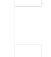
| Here I am drawing a window frame in 2D plan - the opening is already drawn (see note at end of example for information on orientation) and the problem is to draw a frame 100 mm thick and the front face of the frame must be 150mm (0.15m) from the outside face of the wall... | ||
|
|
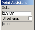
Click on one side of the plan opening - if the arrow indicator does not find the correct corner first time move it by snapping to the point - then enter 150 mm (0.15 m) into the Point assistant Delta offset entry that has appeared onscreen... |
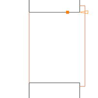 |
| (Above) A window opening in plan - the projecting cill shows the outside wall face | (Above) The orange indicator produced by use of the 'Offset by line' tool assistant | |
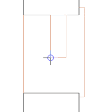
| Press 'Return' to enter the offset value and the Rectangle command reappears with a rectangle anchored to the (here) top right corner and 'rubber banding' a rectangle as you move the cursor around. If you look in the main command line (the line that gives you prompts) you will notice that Allplan is now prompting 'Place a diagonally opposite point or enter the length'. Type in -100 (or -0.1 if working in metres) and press 'Return' - it has to be negative because we want the offset to be left of the anchor point... | ||
 |
Now
(Right) you can see that the box is constrained in the 'x' direction
but still 'rubber bands' in the 'y' direction. Allplan now prompts you for the 'y' value with... 'Place a point or enter the width' - here the simplest way to complete the rectangle is to use a 'snap' to just connect to the other side of the window. |
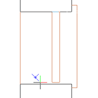 |
| (Above) After entering the offset the Rectangle tool becomes active again with the top right corner anchored to the position established by use of 'Offset by line' | (Above) After entering the 'x' dimension of the rectangle the box is now constrained in one direction - snap to the other side of the window to complete the rectangle | |
|
|
 |
 |
|
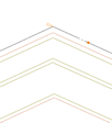
| (Above)This is the ridge tile in elevation completed. | (Above)The small orange dot shows where the line was first clicked after invoking the 'Offset by Line' tool and a faint arrow at the intersection shows where the distance is being measured from - the illustrated value is just the distance from the apex to where the line was first clicked - replace this with the desired value - here 150 mm (0.15m) | ||
| Click
the apex of the rooflines to create one side of the ridge tile, Do not be alarmed by the rubber banded line that seems to dance about on screen when you have completed this stage - either Esc out of the tool or just select the next command which automatically ends the previous command before starting the new one... |
|||
 |
 |
 |
|
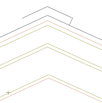
| (Above)The right side completed. | (Above) Repeat for the left side and then use the 'Drop Perpendicular' tool to close the ends. | (Above) Completed using the 'Drop Perpendicular' tool. | |
|
|
||
|
|
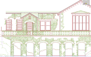
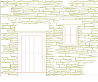
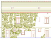
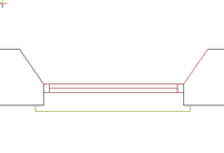
Even in the age of rendered models - there is still a need for 2D elevations! |
 |
Anyway... Click the Smartfit tool icon (as above) , select your pattern and Click the OK tick button - Allplan asks you to enter the outline of the region to be filled with the tiled pattern. You can do this manually but the 'Outline autodetect' tool is available.
Update 09.10.01 - see also Tips & Tricks Page 4 for a couple of issues.
| In this example the left reveal has already been done - there are various ways to set this up - this method demonstrates using the measure command as an interrupt to the chamfer tool... | ||
|
|
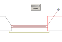
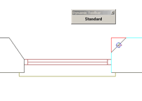 click the Chamfer tool and click one of the elements to chamfer - here I have clicked the vertical element first... |
|
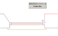
| the chamfer tool gives guidance in the command line but also displays a dynamic tool bar as shown top right - click on 'standard' to follow this method - confusingly the toolbar now displays 'centre line' but that is just the next option... | ||
|
|
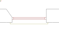
 Allplan now asks for a reference point on the other element and rubber-bands a line from where last clicked - note the 'angle' dynamic tool bar offering yet more options for making the chamfer... |
|
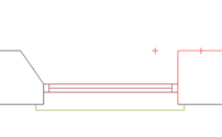
| now assuming - as often happens to me, that you have forgotten to set up a construction line to snap the final point to - click on the 'Measure' tool, 'length' and then click on the leftmost point of the left reveal - then using 'linear snap' obtain the horizontal dimension to the window - then click the result 'L= xxx ' in the measure tool results window that appears... | ||
|
|
 |
|
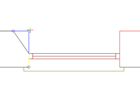
| Allplan
inserts the measurement into the waiting 'Chamfer' tool and 2 option
points appear - click on the one you want - here the right hand one... and the chamfer is made.... spot the mistake?... the chamfer is drawn in the current pen and not the pen of the 'wall' outline - something to check for! :-) |
||
|
|
Most Allplan 2D drawing tools exhibit a remarkable flexibility in use which is not apparent without a bit of 'digging'. It really is a credit to the programmers the way they have anticipated what the draughtsman (or woman) is trying to achieve at a practical level. |
|
Click 'Modify Format Properties->' then click the tick boxes for the line type or thickness you want to change TO.
In the Filter Assistant click 'Filter elements based on a pen' or use the 'double chevron' button to match an existing line on the drawing. At the command prompt it will ask you to Indicate the Elements to be modified - draw a box round all the elements required using the middle mouse button (you can further use the polygonal boundary tool here or more filter options (see Top Tips page 2).
Top of Page
Home
¦ Park
Issues ¦ Services ¦ Local
Links ¦ Technical Section
Allplan FT Users Page 1
| disclaimer - please read! |
Site © WSA 2015 |