| William
Sutherland Architect |
|||
|
|
|||
![]()
Click
Here
to Return to
Allplan FT
Users Page 1
Office
Address Cluan
Rydal Road
Ambleside
LA22 9BA
015394 34489
For
location plan
see Local Links
|
|
 |
User Pages for Allplan FT New User's Survival Guide... |

| Jump to other NUSG Pages... Page 1 | Page 2 | Page 3 |
 Plotted drawing files have mixed scales... if you find that your
plots have some drawing files within a fileset plotted at the wrong
scale it is caused by reference files not picking up the current scale
from the active drawing file when you have changed scale while working
- visually they are OK but when plotted they retain their original scale
if it was different... (I'm not explaining this very well!)
Plotted drawing files have mixed scales... if you find that your
plots have some drawing files within a fileset plotted at the wrong
scale it is caused by reference files not picking up the current scale
from the active drawing file when you have changed scale while working
- visually they are OK but when plotted they retain their original scale
if it was different... (I'm not explaining this very well!)
Anyway - to avoid this go into Options -> Plot Layout -> and activate the option Keep drawing element scale. This will force all drawings in a fileset to come into the layout editor at the Relative Scale of the first drawing in the fileset - of course you can still change it using the dynamic toolbar when bringing it in to the layout editor - this just ensures all drawing files within the fileset are at the same scale.
-
Roofcovering and rafter offsets... as far as I can tell Rafters
offset DOWNWARDS and Roofcoverings offset UPWARDS from the line of the
roofplane.
Thus if you set an offset of zero (the default) in the rafter setup dialog for 'Height above roof' the top of the rafter will align with the roofplane. To have the bottom of the rafter align with the roofplane you need to insert a positive value equal to the thickness of the rafter.
However!... watch the dynamic toolbar that appears when you create rafters - if it is set to 'RCover' rather than the default 'Plane' then the top of the rafters will align themselves to the underside of the roofcovering and values entered in 'Height above roof' will reference to the underside of the roofcovering - positive to go upwards and negative to go downwards.
Similarly, setting an offset of zero (the default) in the roofcovering dialog for 'Height above plane' will make the thickness of the roofcovering go upwards leaving the bottom of the roofcovering in line with the roofplane.
To make a space between the bottom of the roofcovering and the line of the roofplane enter a positive value for the offset.
It is logical I suppose but it could be made more clear in the dialogs.
 Click the image for a larger version (17Kb)
Note that if you use an offset in plan to the roofcovering outline when outlining it you may find that once beyond the line of your roofplane, the default planes values take over and the bit of roofcovering projecting beyond the roofplane is on the floor!
Safer to define the roofplane to extend as far as you want the overhand to go, use a negative offset to the rafter feet ('Rafter tail') in the rafter dialog to pull them back from the bottom edge and let the roofcovering overhang them a bit.
Of course if you have a roof at lower level running under another roof it would be best to create it in a separate drawing file.
-
I've moved the walls but now the slab is wrong... A really useful
tool is this one
 'Reshape
hatching.pattern, fill or Architectural area' available in several
modules including Walls, opening, components and Draft and Paint - but
most usefully available if you Right-click a slab.
'Reshape
hatching.pattern, fill or Architectural area' available in several
modules including Walls, opening, components and Draft and Paint - but
most usefully available if you Right-click a slab.
This will allow you to add or subtract areas of slab in plan (look at the options on the dynamic toolbar and watch out for the auto-outline toggle in the point assistant toolbar defaulting to ON).
Remember also that the wonderful 'Modify offset' tool will also work on
slab edges. (Click the same line twice just to move it freely - but
watch for any attached lines - it is a 'stretch' operation in all but
name).
'Modify offset' tool will also work on
slab edges. (Click the same line twice just to move it freely - but
watch for any attached lines - it is a 'stretch' operation in all but
name).
-
How do I bring in drawings/symbols/patterns?... The procedure to
import symbols, drawings, patterns into Allplan is simple - once you
know how... this
link (also available from the main page) takes you to a detailed
guide.
-
Using a template project... I have tried several ways of copying
details from a template project - i.e. a blank project with filesets
and drawing names setup which you then copy into each new project as
a ready-made structure - and the best way for me is to open Project
Pilot, right-click on your template project name in the list
in the left-hand window and choose 'Copy to...'
from the menu that appears. Then enter the name of the new project in
the box that appears next... and that is it.
I used to set up the new project first and then copy the filesets across but sometimes had problems - the above method is much better.
Update: you can make any project structure a reference structure just by right-clicking on its name in the Project Pilot list and choosing 'Structure..' which gives you a dialog where you can save that particular project structure under either 'Office' or 'Private' for use in other projects. Thereafter when you create a new project there is an extra step available where you can click on a saved project structure to be adopted for the new project.
However be aware that this procedure only copies the file structure and not the contents of drawing files set up in your template project - e.g. title blocks.
Another method - copying the actual layer files across I have mentioned before here (scroll down the page).
-
Some selection tips... After a while you develop such quick selection
methods that they become second nature. One I use all the time is,
after clicking the command and before trying to select anything, just
right-click in an empty area of workspace (it actually invokes the
'open brackets' feature) and you can add to the selection by clicking
elements or surrounding them in a left-click-and-drag
box or a middle-click and then drag and
middle-click box - note that to unselect elements they have
to be clicked exactly, you cannot unselect by using a selection box
(if you see what I mean). When you have all the elements you want
highlighted just right-click again in an empty area of workspace (invokes
'close brackets') and you can then continue with the original command.
Note that if during this process one of the elements just flashes at you and you wonder why you cannot select it, it is because the 'congruent elements' tool is switched on - it can be found on the 'filter
assistant' toolbar. This tool allows you to step through elements
lying on top of one another by pressing the Spacebar on the keyboard
- press 'Enter' to select the one currently flashing when the tool
is in operation.
elements' tool is switched on - it can be found on the 'filter
assistant' toolbar. This tool allows you to step through elements
lying on top of one another by pressing the Spacebar on the keyboard
- press 'Enter' to select the one currently flashing when the tool
is in operation.
-
How do I line up drawings in plot layouts? After trying out various
methods and checking the online help the available solutions seem
to be as follows:
1. for 'congruent' drawing files - i.e. where the drawing file will fit directly on top of drawing files already placed in the plot layout - just left click within one of these files and the new file will be placed correctly - as an alternative you can double right-click in a blank area of workspace.
2. for drawing files that you wish to be horizontally or vertically aligned with another drawing file already placed in the plot layout click the border of the file already placed - this is the line around the placed file. Click the vertical border to 'lock' the new file in the 'x' direction or click the horizontal border to lock it in the 'y' direction.
3. for further manipulation I find that 'element' snap works with the drawing file boundaries, 'point' snap works with file boundary line endpoints and the plotter page margins outline endpoints and if you have linear snap enabled (I use it all the time) then with the middle mouse button you can align to drawing file boundaries or the plotter page margins outline.
-
Dynamic toolbar 'Cursor snap'
This option on the dynamic toolbar is very useful but poorly explained. The obvious use is to set the angle and you can then draw a line constrained to multiples of the set angle - less obvious but more useful is to enter a length in the command line whereupon Allplan prompts you for the direction. This is useful for drawing up measured surveys in 2D among other things (great for bay windows). One curious feature is that endpoint snap seems to be operational while using this feature but no 'cursor tip' appears and linear snap also works (if enabled) with the middle mouse button.
Update October 2004 Allplan 2004 -in Allplan 2003 'Advanced Point Entry' was brought in and this is improved slightly in Allplan 2004. You can turn it off via the Tools menu at the top of the screen but it is so good once you get the hang of it that I recommend you leave it enabled.
Here is part of a posting I did on the subject to the AllplanForum.
Dynamic toolbars are context sensitive - so only filters or options relevant to the tool or command you are currently using will be available.
However in the case of the point assistant, this is greyed out because the default in v2003 and v2004 is for 'Advanced point entry' to be turned ON.
In v2004 the toggle switch to turn this ON/OFF is under 'Tools' on the top menu bar. (In v2003 I think it may have been under the View menu.)
If you untick this to turn it OFF, then the point assistant will no longer be greyed out once you select a tool. However the Advanced point entry is much better left ON,... it can be a bit tricky to understand how to use it, but it is very clever and a big aid to productivity reducing the number of clicks and construction lines required to place points and lines etc.
Snapping gnerally is set from the bottom option called 'Point entry options' on the right-click shortcuts menu after you have clicked a tool button such as 'Line' (Ctrl+L).
FWIW I turn them all on apart from grid snap.
I enable linear snapping - 'Show linear snap' - which gives alignment lines to points already drawn, but...
then back in the top level menu 'Tools->Options->Global Options' in the tab called 'Settings' I choose the 2nd option for 'Middle mouse button assignment'.
Doing this means that the lines for linear snap are not constantly displayed on screen, but are available by holding down the Ctrl key on the keyboard.
It happens to suit me this way but everyone will have their own preference.
It took me a long time to work out how best to use the features provided by Advanced Point Entry.
I find it easiest to think of it as providing an offset distance to a point already onscreen.
Say you wish to draw a line starting 2 metres along a horizontal line already drawn.
Click the Line command (Ctrl+L), place the cursor - don't click, just let it hover over the point - at one end of the existing line - an orange X should appear when a snappable point is present under the cursor.
Now, leave the cursor in this position without clicking and look at the X and Y entry boxes in the dynamic toolbar at the bottom of the screen.
If a real point is selected these boxes have a faintly yellow background which should be the case in this example.
Still without clicking key in a number for distance... as you enter the number the orange cursor will automatically offset itself right along the line since you are inputting to the X offset (pressing TAB key would switch to the next box along, the Y offset and using a minus sign before the numbers would give an offset left). When the distance is entered press the Return/Enter key on the keyboard and the start of your new line will have been positioned at the offset you have keyed in along the original line.
If the line had not been horizontal or vertical then you could right-click on the existing line and choose 'Reference point' which will position an offset arrow at the nearest point on the line that the system can find. You will then see the distance in the box in the dynamic toolbar from your right-click cursor position to where the system has placed the little orange arrow and you can then type in the distance you want.
Once you understand the Advanced Point Entry method it is incredibly useful for positioning elements without needing to draw construction lines.
-
The non-Windows™ menu options ?
The '-, +' and 'arrow over a line' symbols in boxes at the top of menus have bemused all of us however as far as I can tell they work like this..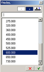
Delete: Move the highlight to an entry in the list using the arrow keys and then press the '-' sign box and it deletes the entry from the list... (clicking a list entry just selects the chosen value and the menu closes - use the Down arrow key on the keyboard to jump the cursor into the list if it is in the command line)
Add: Click the '+' sign box, enter a value in the command line and key 'Enter' and the value will be added to the list... and the menu closes.
If you click the Green tick mark to close the menu the value is returned but not added to the list.
Edit: Click the 'arrow over a line' symbol and it puts the highlighted entry into the command line, the arrow keys on the keyboard can then be used to run up and down the list and the highlighted entry is updated in the command line - presumably for editing. If the entry is amended, clicking the '+' box clears the line but clicking the 'arrow over a line' brings back the deleted entry (?). To add the amended or new entry to the list the '-' box needs to be highlighted and you need to use 'Enter' to exit the menu - as mentioned above for 'Add'.
Update Sep 2005 I've never got the hang of these boxes! Still not sure if the above is correct.
-
Detail Module Tools are greyed out! - This caused some headscratching...
too obvious :) - you need to create a Fileset before these tools are
made available.
-
Save your designs - Save, save, save your stair, wall, roof etc.
designs that you use regularly as a style so that they can be recalled.
Use the store and retrieve buttons at the bottom left of the parameter dialogues found on most architectural tools (see left).
Some users also set up a 'Com' drawing file which contains all their favourites so that using the Allplan 'com' technology you can pick up the attributes of an existing element by right-clicking or double right-clicking on it - although personally I am not so keen on this as it can lead to confusion over which drawing file the new elements are being created in.
-
How do I make the default layer invisible/frozen? - You can't apparently...
therefore it is quite a good idea (especially if like me you do not
bother with layers much) to set the drawing current layer to 'DE_GEN01'
or anything else from the 'Set...' option in the format toolbar before
you draw a line - or you can press 'Ctrl + 4' to bring up the Layers
dialogue (a bit daunting initially but very good) - note that if you
press 'Ctrl and the '4' on the Number pad this brings up the Left Elevation
and not the Layers dialogue.
Update 16.08.01 - just discovered that autoassign of elements to layers is turned on by checking an option in the Layers dialogue - see Tips and Tricks page 4
-
Linear snap has stopped working! - Linear snap is a feature where
guidelines are automatically displayed when the cursor is aligned with
a point onscreen - when enabled, snapping to theses lines is done using
the middle mouse button by default.
Assuming that you have turned on Linear Snap in the first place - it's done from the 'Point Snap' icon the one that looks like a plus sign in the Point Assistant toolbar.
If the linear snap guidelines no longer display - Look in 'Tools->Options->Global Options' and click the 'Settings' tab.
If you have enabled the second option in 'Middle mouse button assignment' then linear snap is changed so that the Ctrl key needs to be pressed for the snap lines to display.
-
My roofcovering will not go on the dormer! - This one still catches
me out. It also applies if you have a roof frame with a valley in it.
The whole issue relates to a setting in Roof Covering Properties. There are 3 buttons under 'Input type'. If the middle button is engaged then Allplan omits the roof covering around dormers and other roof shapes. It is safer generally to stick to the first option.
-
Allplan v17 is getting slower and slower in 2D! - I have found
that if you enable the 'Display List' option
in 'Show/hide' then it seems to work best
with 3D data. When working with large 2D drawings I find Allplan getting
very slow at 'picking' elements with this option turned on. If I turn
off the 'Display List' option then things
return to normal.
Update May 2003 Allplan 2003 this is fixed :-)
-
How do I copy a project to a laptop or another PC? - The simplest
method for copying projects between different machines running Allplan
is to use the Backup facility.
From the ‘Services’ application use the ‘Configure->Backup Device’ to set the location for backups on both computers.
Then also from ‘Services’ use ‘Data Backup->Backup->Named Project’ and choose your project from the list presented.
This will then make a zipped backup of the project.
Using Windows Explorer make a copy of the directory that you defined for backups – if you used the default one it is in I think one of the /Nem/ subdirectories, although I prefer to set up one with a more obvious name.
Copy this or the contents to the backup folder – each zipped project has a zip file and an associated ‘inf’ file – but they are just numbered – unless you open the ‘inf’ file in a text editor you will not know which project is which assuming you have a few backed up here – this is why it is easier to copy them all across.
On the laptop or other computer start Allplan and create a new blank project but called something similar to the name of the project you are copying.
Then run the ‘Services’ application on the laptop and choose ‘Data Backup->Restore Backup->Named project’.
You should be presented with a list of projects including the new blank one you just created – select that project – OK to the ‘start restoring backup… ‘ message and you should now see another list – this time of the projects in the backup folder on the laptop.
Choose the project you want to transfer and click ‘OK’ .
Exit ‘Services’ and run Allplan – when you open the project you created it should now be a copy of the one on the original machine.
Update May 2003 I am told that you can export projects from the layout editor commands in NID format which apparently takes all textures etc with it. Then just import this file into the destination PC. I've not tried it but it sounds as though it should work.
| Jump
to other NUSG Pages Page 1 | Page 2 | Page 3 |
Home
¦ Park
Issues ¦ Services ¦ Local
Links ¦ Technical Section
Allplan FT Users Page 1
| disclaimer - please read! |
Site © WSA 2015 |