What is CAD?
A confusing but prevalent three letter acronym it stands for Building Information Modelling perhaps, see below
Computer Aided Design for Architects has been around for decades but still has its pros and cons - see below
What is BIM?

How CAD Works, what is BIM, and do we care?

Of Vectors and things
Until relatively recently CAD software was exclusively Vector based.
This means that when you drew a line on the screen it was stored in the computer as a start point, an end point and a direction (you may have done this in Maths at school).
Originally the start point and end points had only 2 co-ordinates - x and y - but with the advent of 3D programs a z co-ordinate is now usually present as well (but set to zero for 2D drawings).
The CAD programme stores a list of all these vectors in memory and when they are moved, cut, deleted etc. updates the list.
When you save the drawing the list is saved and some tidying up of the list usually takes place without you noticing.
Apart from the basic start, finish and direction of a vector other information called 'attributes' are used to describe whether say, a line is dotted or what colour it is. Already you can start to see why CAD programmes are complex bits of software and why 'stability' is a prized quality ( the phrase 'problems with stability' is used instead of 'the programme crashes').
Rubber banding and snaps
The fundamentals of CAD have not changed for many years.
You click your mouse or pen or whatever pointing device you are using at a point on screen which starts say, a line.
The pointer can then be moved around with a 'rubber band' line (as though you have one end of a rubber band pinned to a board and you are moving the other end away from it).
This is where 'snaps' come in.
All CAD programmes feature a method of fastening the other end of the 'rubber band' line to a specific point.
If no 'snap' is switched on then you can click your mouse or pointing device anywhere on screen and you have a line drawn on the screen.
There are many different 'snap' methods - the commonest are 'end point snap' where the on-screen cursor will jump to the end-point of a line already drawn and 'intersection snap' where the on-screen cursor jumps to the junction of say, two lines that cross.
All these 'snaps' only operate when your on-screen cursor is within a set distance (on the screen) of the point or intersection. Switching between 'snap' modes is usually done by clicking on a menu option - it varies from programme to programme. Once you have mastered these basics the rest should follow....slowly.
I found it useful to remember secondary school geometry lessons about 'tangents' and 'arcs' etc. It is no coincidence that the number of curved buildings has increased since CAD became commonplace!
Beyond simple lines and circles
Most CAD programmes have features included or available as an extra which will take some of the labour out of drawing repetitive or awkward tasks.
Automatically inserting a window into a wall for example.
This is achieved by little computer programmes known as 'Macros' or 'Scripts' specially written by the CAD package authors or sometimes by a 3rd party company.
I have used several CAD (computer aided design) systems over the past 30 years and still have licences for:
Drawing Express by Trial Systems Ltd and
Autodesk Revit as part of an AEC subscription
The first two listed packages are 2D drawing software with 3D modelling capabilities although serving slightly different markets.
Drawing Express is very popular with Architects who like a pen-based interface plus exceptional user support from the developers Trial Systems Ltd based in Burton-on-Trent, UK.
Allplan is very powerful CAD software with a long and impressive development history from Nemetschek in Munich, Germany.
Revit was a start-up developer product eventually bought by Autodesk and now forms the basis of an entire platform of architectural, services and structural versions.
Revit is quite young as CAD software goes - much of the established CAD software was originally developed decades ago. For my purposes I find it the best all-round product for 3D architectural design but there are many packages on the market, each with its own particular really nice feature.
Users become very defensive about the product in which they have invested time and effort to learn. There was a Revit vs Archicad vs VectorWorks vs ....' ongoing, 'mine is better than yours' sort of thing in online forums for some years but this seems to have settled down somewhat possibly due to the overwhelming dominance of Autodesk and Revit in the marketplace now that contractors as well as architects are investing in what is called 'BIM' (see later all about BIM).
Currently I have an Autodesk AEC subscription which not only gives me Revit that I use daily but also 3D Studio Max and full Autocad, and a few other useful packages.
I have never really taken to Autocad but it's file format known as DWG (and its simpler sibling DXF) are widely used as an exchange format between CAD systems.
Because DWG is an Autodesk exclusive file format, other CAD software developers have had to 'reverse engineer' a way of opening these files. To make this harder for competitors Autodesk have traditionally updated their DWG file format every 3 years, although they let this go at the last revision.
I switched to a model based design process back in 2000 (i.e. I build virtual building models in software running on a computer) using Allplan and changed to Revit in 2007 as my main design tool when it looked to have matured into the best all-round AEC 3D CAD product.
Computer Modelling All Projects
I set a personal goal of modelling all projects on computer in the late 1980s but it took until the early 2000s to fully achieve this.
An early use was in designing the complex roofscape of the shop for Hawkshead Sportswear at Hawkshead (below)

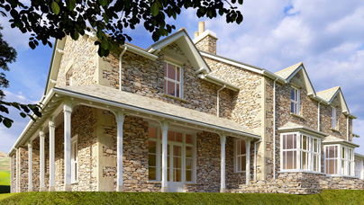
Constant investment in training and new technology allows computer modelling to now be a seamless part of client discussions on design, and detailing with contractors. Below is a recent house design in Grasmere. This is a computer rendered image created from the Revit building model.
Bitmaps
If Vectors are lines, then Bitmaps are images made up of dots (the dots making up an image on a monitor are called pixels).
Software packages that allow you to edit digital or scanned photographs on your computer screen are Bitmap editing programmes.
Adobe Photoshop is typical of this type of software.
To confuse things some advertised Vector based drawing software is not CAD at all but are Art Drawing programmes.
Adobe Illustrator fall into this category.
The difference being that with a CAD package you are working to a scale and measurements, whereas with an art package you are using your 'eye' to judge proportion (but vectors at their most basic level are normally interchangeable as files between CAD and Art type software, with a little effort)

It's drawing Jim, but not as we know it
That was elementary but if you have grasped the basics that will do for most people.
The advent of 3D CAD at an affordable price point on hardware and software has transformed the role of CAD in designing objects and buildings. Understanding how it works in any great detail is probably a bit pointless for the average user - just enjoy the features and admire the skill of the programmers.
That said here are a few beginner's notes on the subject.
For Architects only used to drawing with a pen and pencil there are two conceptual leaps to make in a change over to 3D CAD.
The first is to grasp the basic idea of how CAD works (see above) in 2D, replacing the physical pencil with the virtual,
and the second is to understand the object orientated nature of 3D CAD systems.
'Object orientated' just means that you assemble your building from a set of components rather than by drawing lines.
These components have a certain amount of 'intelligence' in that they know that they are part of say, a wall and the wall can interact with windows, doors and roof - OK, so you have to see this in action to understand how it works but essentially it keeps the building design 'live' so that changes can be made at any time.
Traditional 2D (i.e. plans, elevations, sections) views are generated from the 3D model by the software and can be arranged on a drawing sheet for plotting.
Unfortunately many Architects are locked into the idea still of producing a 3D view as a special service to clients.
Site Map
|
Planning Maze
|
|
Trade Gadgets
CDM2015
|
|


William Sutherland rias riba
Chartered Architect
Director
Cluan, Rydal Road, Ambleside LA22 9BA
Tel: 015394 34489


