William
Sutherland
Architect |
| |
|
|
 |

Click
Here
to Return to
Allplan FT
Users Page 1
Office
Address Cluan
Rydal Road
Ambleside
LA22 9BA
015394 34489
For
location plan
see Local Links
|
 |

|
Tips
& Tricks...
 |

User
Pages for
Allplan FT |
|
| Apply
2D lines to Door Symbols... |
|
|
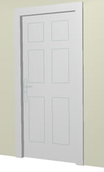
This
came out of a general discussion on using the Smart Symbol Designer
- you can do a lot more with it than you realise but it takes a lot
of effort initially to understand what buttons do what... Here we
discovered how to apply a 2D symbol saved earlier to the face of a
door. It seems to be applied to the Opening face only as 3D lines
- but back to front(!) and is stretched to fit the door frame - here
I saved a symbol with a construction line outline. The 3D lines now
show up in elevations etc but are in fact in line with the door frame
plane and not the doorleaf - although I doubt you would notice.
Once you create your doorleaf, click on the 'get from folder'
button... |
The
view in the animation window - left clicking the door direction
when placing the symbol would probably change the side which
receives the lines but it would need trial and error to work
it out.
Remember also that 3D lines do not show up in fully Raytraced
renders. |
Once
symbol retrieved from library folder it appears in the display
- but if you compare how it is shown here and how it displays
on the opening side of the door you will see that the handle
is on the wrong side... |
|
| Rabbet
applied to multi-layer wall... |
|
|
Allplan 2004 includes a rabbet tool for multiple wall layers.
[pre Allplan 2004] This
is something I have been trying to do for months - apply a tapered
splay to the reveals of a window in a 4 layer wall. The new Building
Regulations in England have made life a bit easier here as the cavity
will have to go up to 100mm wide (not quite sure what we are going
to do with the DPC though!)
 |
Create the window as normal, in my 4 layer wall the outer layer
is a 225 mm rubble stone facing purely for appearance.
I then draw a 2D diagram (as shown) to measure the width of
the splay at the inner face of the cavity and then the inner
face of the wall.
 use the 'rabbet' tool first on the cavity layer but set the
internal reveal
use the 'rabbet' tool first on the cavity layer but set the
internal reveal |
depth
in the tool properties to the cavity thickness - here 100mm and the
splay width to the value measured on the 2D diagram - here it works
out at 57mm. Note that you need to click towards the inner face of
the layer in order for the splay to angle the correct way.
Click on rabbet properties again and then set the values for the internal
wall layer - here they are 200mm for the internal reveal depth and
114mm for the splay width. Applying these to inside the line of the
inner wall layer will make the splay or rabbet line up with that of
the cavity layer.
Note the cill line does not meet the rabbets - this was fixed in v2003 I think. |
| Text
in non-standard pen colors... |
|
|
The
only method of obtaining coloured true type fonts seems to be to assign
a pen colour to the text (using Modify format). I use pen 15 (I think
more pens will be available in v17) and then set the output colour
in the
'Plot Layout->Setting->Pen and Color assignments...'
dialog.
 |
However, if you want a non-standard colour you can enter RGB
values in the boxes next to the output colour (see left)...
and if you want to know how to find the RGB
values of a colour you want to copy....well, if you can open
the document containing the colour you want to copy in a package,
just to get it onscreen, you can then |
use the
'eye-dropper' tool in a bitmap editing package like Macromedia Fireworks
or similar to pick the colour off the screen - and even though the
'eye-dropper' may disappear when outside its own application this
usually works. From within Fireworks or other package it is normally
possible to examine the details of the colour in RGB format (among
others). |
|
|
|
If
you want to check the standard Nemetschek colour range on screen against
the plotted output there is a handy chart (from the webboard
this one).
 |
Open ProjectPilot and Right click on Path to External Buffer
and navigate to \\Nem\Allplan\New
(this is the \Nem on the programme files partition rather than
the \Nem on the data partition). In the 'Drawings'
folder there are a list of interesting files. The colour chart
is No 25 on my system. Copy it into a spare drawing file, exit
from project pilot, open the drawing file and then the layout
editor and bring it in and plot it in the normal way. |
Click the
chart for a larger version (32Kb) |
| Get
projection from animation... |
|
|
Another
use for 'From animation' option (circled)
-
click the little 3D view icon  at the top of the window after setting up the animation window so
as to be visible alongside the isometric.
at the top of the window after setting up the animation window so
as to be visible alongside the isometric.
 |
For when the standard isometric view does not let you get the
view you want to manipulate elements. By keeping the animation
view handy you can use it as a positioning guide and then click
and then 'From animation'. If the
animation window is slowing down operations just use 'Tools->Options->Animation'
to set it to wireframe view (yes, I know it would be nice to
combine both views! :) |
|
| Rotate
3D objects to match angle... |
|
|
 As we all know, the Rotate tool has an option to point at a reference
line and direction line after the elements and origin are selected
(it allows you to align one element with another).
As we all know, the Rotate tool has an option to point at a reference
line and direction line after the elements and origin are selected
(it allows you to align one element with another).
However this does not work with 3D objects. It works with lines and
Archit. elements only. In plan view, if you try to use it with a 3D
object when you point at a reference line, when prompted by Allplan,
the selected object goes into 'free rotation'. (Archit. elements only
do this if you click a point here)
 One way around this is to use the Measure tool when Allplan asks,
'click reference line or enter a rotation angle'
One way around this is to use the Measure tool when Allplan asks,
'click reference line or enter a rotation angle'
Measure the angle between an edge of the 3D object and the element
you wish to align it with and when the value appears in a little box,
click the 'A=xxx ' value which activates
the rotation (measure the angle in the direction of the rotation).However
you cannot align two 3D objects this way (nor an Archit. element or
line to a 3D object) - the measure command gives an error message
'Lines are slanting'... well, not always!..
sometimes it does and sometimes it does not -
for
those times when it does...
Unless
someone knows of a better way, in this situation I just draw a construction
line along an edge of the 3D object for Allplan to 'see' and then
either method works.
I also notice that the 'Angle' value remains in the command line and
can be reused later. It
gets more interesting if you use the 3D option in Rotate (or just
use 'Rotate 3D elements' in the 3D modelling module - seems to be
the same tool) to rotate 3D objects in the elevation and isometric
view when the measure tool returns 3 values you can use 'A2D, W3D
and DHA' - but I have not really worked out how to implement these
- nor the 'rotate 3D entities' tool despite the diagram in the Help
file. |
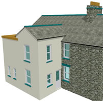
| Arched
window in gable... |
|
|
This
is an 'old chestnut' but it still catches me out... :)
In a gable wall controlled by planes Allplan will object if you try
to insert an
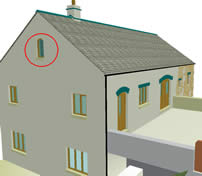 |
arched opening crossing the plane boundary as arched openings
have to be wholly contained within a plane - and gables are
actually 2 planes meeting on a line under the junction of the
roof slopes.
The answer, (I looked it up in the webboard archive) is very
simple once you know - just set BOTH top and bottom levels of
the opening to absolute levels - i.e. use the icons 3rd from
the left in the Setup dialog - the triangle shaped ones. |
|
|
|
|
Here
is a neat trick - on work to existing buildings I like to mark alterations
to construction in red and put the new elements on a separate drawing
file.
However this means that  copying any items from the existing construction in the 'edit'
mode drawing file leaves them in the original drawing file.
copying any items from the existing construction in the 'edit'
mode drawing file leaves them in the original drawing file.
 |
Instead use the Copy to Clipboard
tool -  Click on the element or draw a selection box around the elements
you want (here I have copied the door from top right to the
new wall at bottom left), click on
Copy to Clipboard and then on
Click on the element or draw a selection box around the elements
you want (here I have copied the door from top right to the
new wall at bottom left), click on
Copy to Clipboard and then on  Paste from Clipboard -notice
that you are now offered the Dynamic Toolbar and you can use
the '+' and '-'
keys to rotate the elements to be pasted.
Paste from Clipboard -notice
that you are now offered the Dynamic Toolbar and you can use
the '+' and '-'
keys to rotate the elements to be pasted. |
When
pasted the elements copied are now in the active drawing file and
thus will interact with the Archit. elements (here drawn in red). |
| Join
Wall with Line - by Layer... |
|
|
 The Join Wall to Line tool comes with
a dynamic toolbar (pictured) with the option 'By
Layer' when dealing with multi-layer walls which when clicked
allows
The Join Wall to Line tool comes with
a dynamic toolbar (pictured) with the option 'By
Layer' when dealing with multi-layer walls which when clicked
allows
 |
you to selectively trim construction layers to lines.
Incredibly useful... (I wish I had noticed this months ago!)
The strange thing is that the dynamic toolbar does not appear*
until after you have pointed at the line and trimmed the wall(!)
The 'By Layer' option works similarly
with  Join Walls as well.
 |
Update
05.02.02
*We
think this may be a bug - the 'By Layer'
dynamic toolbar appears correctly when the command is invoked from
the relevant toolbar, it is only when accessed from the right-click
shortcut menu that the dynamic toolbar does not appear first - in
fact if you look carefully it does appear for a fraction of a second
and then disappears until you have first used the command whereupon
it reappears correctly for the next use.
|
| Text
orientation settings... |
|
|
A
recent discussion on the webboard
reveals that this option highlighted below is what controls the clever
way Allplan flips text to be readable even if you
 |
rotate
or mirror it. Uncheck the option to leave the text upside down
or mirrored. The option is available from 'Tools->Options->Text'
The other options are also useful and fairly self-explanatory.
I like the 'Add angle to system angle' option as this allows
text to be input at an angle without having to set it in the
text editor - just by using the 'System Angle' tool

I have never quite got the hang of the 'Auto-select pen...'
option - I prefer to choose my own pens and for TT fonts I don't
think it makes any difference. |
|
Top of Page
Home
¦ Park
Issues ¦ Services ¦ Local
Links ¦ Technical Section
Allplan FT Users Page 1
|