William Sutherland

Architect
 

Back to Allplan Users Page 1
Click Here
to Return to
Allplan FT
Users Page 1


Office Address Cluan
Rydal Road
Ambleside
LA22 9BA

015394 34489


For location plan
see Local Links



Ambleside (TR) my office is down there on the right somewhere!
Tips & Tricks...

User Pages for
Allplan FT
  Jump to other Tips & Tricks Pages
Page 1 | Page 2 | Page 3 | Page 4 | Page 6
Page 7
| Page 8

If autolayers stops working...

Not sure why, but sometimes the 'Auto-select layer with menu' function stops working (on the 'Format->Select, Set layers' dialogue). To re-enable it I uncheck the tick box, then 'Apply' and then recheck the tick box, and 'Apply' again, 'OK' out of the dialogue. This seems to make the 'drop down' layer list box in the Format toolbar work properly again so that it offers the full range of layers appropriate to the tool chosen.
If you now assign a layer manually then most of the tools will thereafter auto-assign a layer. However, some - like 2D lines - seem to require a layer to be assigned manually and thereafter it will be autoassigned.
It is quite important not to have elements put on the 'default' layer as you cannot do much with this layer.

Save toolbar & other user settings...

You can export the toolbar settings from the 'Tools->Customise' dialogue. Click 'Export' at the bottom of the dialogue and the default location offered is on the drive specified at installation for the program files 'x:\nem\Allplan\Usr\Local\*.*'
Now to backup this file you need to use the services application and click 'Data Backup->Backup->Private Local->Full' - there are some specific options but I suggest 'Full' is the safest as it backs up subdirectories as well.

Remember of course to in turn copy the zipped backup files somewhere safe - you never know when you are going to need them!

A related matter I have discovered is that the drawing files in the empty default project in Allplan - the one that has no name - do not reside on the data drive (as defined at installation) but are actually on the program files drive in the 'x:\nem\Allplan\Usr\Local\prj' directory. Thus the above backup of user settings may also pick up these drawings.
If you are ever in any doubt as to the real location of drawing files then the full path is given when you look at the files from within Project Pilot (in the title bar at the top of the window).
Update - correction 3/02/02 - all projects have the same behaviour - number of files grows and diminishes as created or deleted - there are not 3,000 files actually created when first setting up a new project - I count 22 in a blank new project.
Allplan v2004 -projects are now saved with the name of the project rather than just a number which makes them easier to recognise within Windows Explorer.
Wall axis lines...

cavity wall cannot have central axis You can make wall axis markers visible from
Tools->Options->
Architecture
and then choosing the 'Axis' button
solid walls - offset and central axis types
Update May 2003 Allplan 2003 allows axis to be chosen from the dynamic toolbar when entering walls.
Allplan 2004 - they have refined the axis options further as a toggle to flip sides but it can also be specified anywhere in the wall depth via the new and extensive wall properties dialogue.

Wall The axis position is determined by where you click when the wall is created - if you click directly on the line drawn before the wall thickness is generated then the axis will be central (only available to single thickness walls). More commonly you tend to click away from the original line and this is important because Allplan always seems to put the outer layer of a multi-thickness wall touching the axis. As shown above I usually apply different fills to multi-layer walls so that the wall lines appear in 2D plan and so that you know which is the outside but the axis if displayed also indicates this - note the square boxes at axis 'nodes' which seem to have no function other than indicators of the end of an axis. Note that you can manually edit the pen weights of the lines of the wall layers but unless you save the wall as a symbol they are not 'remembered' if you store away the wall as a 'type' (this is supposed to be fixed in the next version v17
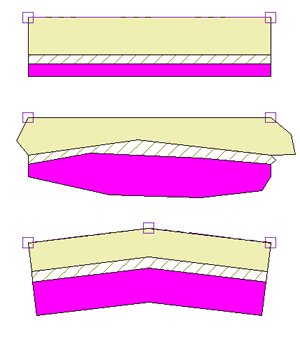
Fold Line The 'Fold Line' tool acts differently depending on whether the axis is displayed or not.
With the wall axis ON, a single or multi-thickness wall will be broken and a new wall section added creating a 'kink in the wall line but maintaining the wall thickness. A single thickness wall with a central axis does not do this but has its thickness altered.
With the wall axis OFF, all walls or layers have their thickness altered.
Here is an illustration of what happens with the wall axis turned ON...

Axis turned ON in Tools->Options->Architecture...

3 layer wall with axis at the top
Fold Line using the 'Fold Line' tool you can drag out any side of the wall or a layer
Fold Line using the 'Fold Line' tool on the axis side not only kinks the entire wall but reasserts the original layer thicknesses too!
2D symbols ...

Get from Library always finding new areas of Allplan - in the 2D Architecture symbol library there is an extra option - number 4 - which just says 'Bathroom Fittings' - unlike the other options which mention a scale. Within this particular library there is a wonderful range of things like a towel on a rail in elevation (honestly!) - well worth a browse for all manner of objects useful for embellishing 2D interior elevations and sections.
Update - Choosing 'Custom' when installing Allplan gives you access to a couple of options about installing some libraries.

Convert Fills, hatches, patterns...

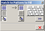
Hatch to Pattern to Fill dialogue
Hatch to Pattern to Fill Here is a curious but useful tool - it is fairly self explanatory 'Hatch to Pattern to Fill' - available from 'Modify->Draft'.
As I seldom use hatching or patterns my main use for it is to change the colours of fills on a 2D drawing globally, or within a part of the drawing. (For architectural elements of course you would use 'Change Archit. Properties').
Just use the double chevron button to pick up the current parameters from a fill (or hatch or pattern) or click one of the 'to' buttons on the right and then set relevant parameters. Allplan will then prompt 'Select hatching/pattern/fill to convert to ...' and you can then just point at fills or enclose them in a selection rectangle to change the colour... or as implied in the name of the tool you can convert fills to hatching or to patterns in a similar manner. It just seem easier this way than using the 'proper' tool -
Change Fill 'Change Fill' which I find very awkward to use.
Yet more fun with text...

Not really a tip as such - just a feature that makes me smile every time I see it in action!
If you select some elements in plan view along with some text, rotate it 180°... and the text still reads from left to right! - and unlike some other CAD systems the parameters have not changed. Very clever... :)

Special Text Characters...

[Allplan 2004 introduces a few other features on text including a character symbol chooser and a Unicode character preview.]
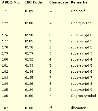
Horizontal Text Special text characters such as the diameterØ (248), or degree symbol° (176) or the Euro € (128) symbol are all entered in the normal text editor:
Enter Text dialogue
Number refs to illustration - in no particular order
1
- click this chevron button to copy existing text into the text editor by just pointing at it on the drawing. Note that it brings in the entire block of text.
2 - click this chevron to copy properties (font and parameters) from existing text on the drawing.
3 - highlight from the drop down list (which records past entries) or enter a new number ( 3 digits ) - Note when entering text in this box use the ISO code numbers even though the box is marked 'ASCII' !! It only displays ASCII codes when you highlight an existing character in the text. (Shift+arrow key)
Note also that if the box is initially empty you will have to press 'Return' after entering the 3 digit code to 'wake up' the insert button at '6'
4
- the ISO box shows the Alt+number combination on the numeric keypad to enter this character in the text (it appears once you lift your finger off the Alt key - Note that you need to type in all 4 digits for it to work and check that 'Num Lock' is ON).
5
- the actual character is displayed here.
6 - An easier method to enter the character at the current cursor position is to just click this button . Note that if this button is 'greyed out' then the character is not available in that font.
Here is a list of common codes from the online Help:


Note that the ASCII and ISO numbers are not always the same... and it is the ISO value that is expected by Allplan whichever method you use to input the value.


The F1 online help is quite good and gives a list of commonly used ISO codes
there is also a link to the Windows™ Character Map application - referred to as the 'Unicode' program by Allplan.

In Windows 2000 this useful program can be found using 'Start->Programs->Accessories->System Tools'... it displays the full character set of any font.
Note to enter super and subscripts and enlarge or reduce text in Allplan you can also use formatting codes directly entered within the text - again the F1 help is quite good - basically for a superscript type %+ before the superscripted text and +% after.
e.g. to get 'squared' - i.e. to the power of 2, the commonest superscript, you would type in the text editor, for 25 square metres:
25 m%+2+%
There are other formatting codes you can use listed in the F1 online Help.

Mount 3D Model in Image... ???

Mount 3D Model in Image Just started using this tool to place a model in a photograph and an error message kept appearing 'The Current View is not a Central View' - which is certainly one of the more obscure error messages I have seen!
3D View What it actually means is that you need to click the '3D view' button on a window control bar and select 'Perspective' instead of 'Isometric'.
Allplan 2004 has more options when clicking this button but I have not explored them yet (although they seem to be fairly self-explanatory).

Exporting model to Cinema 4D...

OK, so you have exported your amazing Allplan model in C4D format, fired up Cinema 4D and Opened the file... so far so good. You can't wait to try out a test render... but... when you do, you get an error message with a list of all the missing textures! The answer is quite simple - in Cinema 4D click 'Edit-> General Settings' and then choose the 'Texture Paths' tab. Here you can browse to all the directories that contain your textures - there is room for many directories - and now C4D can find all your textures no problem :)

Allplan 2004 has a new link method available - a plug-in to C4D which is installed when you install Allplan if Cinema 4D v8.5 is found on your PC.
Texture and surface files are now stored in the project file in Allplan and C4D seems to find them there by itself. (The materials still need tidying up in C4D but Allplan 2004 is much improved over earlier versions in this respect).

Assign surfaces locally...?

[pre Allplan 2004 makes life simpler by including assigning surfaces to walls within the wall properties dialogue]
Assign custom surface properties It is much better to use the 'Assign Custom Surfaces to ...' tool to apply textures to objects locally rather than the 'blunt instrument' of the older tool -
Update May 2003 Allplan 2003 allows surfaces to be assigned from the Properties dialog boxes - not enabled by default you need to check the option.

Assign surface properties 'Assign surface properties'. The simplest method in v16.2 is to save a 3 way window split with the top left window being the animation view, the bottom left being an isometric view and the one on the right the plan view. Right-clicking on an element edge within the isometric view includes the 'Assign Custom Surfaces... ' tool in the shortcut menu but only if Allplan identifies the arch. element - this is why you seem to need to right-click on an edge of the element you want to apply the texture to. One benefit of this method is that the texture only seems to be linked locally and so avoids the slowdown that seems to occur gobally (i.e. in every project) when first opening an animation view when a texture is assigned to a colour by using 'Assign surface properties' - not sure about this but I guess it's the OpenGL buffer being set up and the texture being loaded into it. Also of course it keeps the textures separate for every project rather than acting globally.
See also page on elementary rendering for more on this tool.
Change dimension properties...

Circle Obvious really but it never occurred to me until now that you can change the properties of individual dimensions by right-clicking on them and choosing 'Properties' from the bottom of the shortcut menu. Just change the parameter you want - e.g. mm to ft and ins and then OK out of the dialogue using the green tick button to implement the changes. As usual in dialogues note the the 'double chevron' button (>>) which allows you to pick up properties from an existing dimension by pointing at it.
Update Aug 2005 Allplan 2005 has completely revised the Dimension module.

Measure tool works in 2D & 3D...

Circle The measure tool will now work in all views - i.e. select 'length' option and you can measure heights in elevation or diagonals in the isometric view and the distance is returned as 'L=' with the coordinate values also given.
Note also that you can take successive measurements and a cumulative total is stored as the value of 'L='

Rendered elevations, plans...

rendered elevation
Here is a neat trick since v16.2.
Tick the option to 'Get image from active viewport' after clicking 'Render' from the animation menu. The animation is then taken from the active orthogonal view - i.e. elevation or section or even plan if you have created a horizontal section above the level of the top of the model. If you also select 'Quick Ray' or 'Raytracing' from the 'Method' option in the 'Render' dialogue you will see shadows cast by the sun and/or lighting (set up in the 'Setup Lights' tool.)
Update 26.09.01 - if you want to be really clever click the 3D view button..
3D View before doing the render and choose 'perspective' instead of 'isometric' from the options and the elevation or section will show up in perspective rather than true elevation - pointless but neat! :)
Update May 2003 Allplan 2003 has further improvements to bitmap export and handling generally.
Update Sept 2004 Allplan 2004 has further improvements to editing bitmaps
.. but still no simple way to have scaled and rendered elevations .
Merge walls to heal gaps...

While it does not seem possible to 'heal' gaps in 2D lines, it does seem to work for 3D arch elements like walls. For example -
Wall create a wall, then use
Delete Wall Sections 'Delete Wall Sections' to remove a section of wall (or draw another identical wall in the same plane), then click
Merge Hatching, Patterns, Fills, Archit. Elements 'Modify->Walls,components, Openings->Merge Hatching, Patterns, Fills and Archit. Elements', click on the first bit of wall and then the second. Now they are one entity but the gap remains - you cannot do anything with the gap. To remove the gap use
Modify Offset 'Modify Offset' or Stretch Entities 'Stretch Entities' to close the gap and the wall becomes one complete entity.
Odd but occasionally useful.

Delete/Modify all constrn lines...

Delete A little feature that I like is that Construction Line On/Off construction lines always seem to be assigned to Group 0 (zero). You can see this by right-clicking on a construction line and choosing 'Format Properties' from the bottom of the shortcut menu that appears. Group 0 (zero) seems to be reserved for construction lines. Groups are similar to 'blocks' or 'patterns' in other CAD systems but Allplan makes life easier for the user by automatically assigning a new Group number to each new entity - except construction lines it seems.
Therefore to delete all construction lines (a command that seems to be missing from Allplan although using the filter assistant will do it) just click Delete and then use the middle and left mouse button combination to click on one construction line and they all go!

Match wireframe to animation...

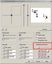
3D View dialogue

Here is a neat feature.
Set up an animation view, switch to another viewport (window),
3D View click the '3D View' button on the window to bring up the dialogue (left), click the double chevron button to match the isometric to the animation.
I have seen this facility used to help create an illustration with an animation part overlaid on a wireframe isometric so that you can see rendered model and a bit of the underlying construction together.

Jump to other Tips & Tricks Pages
Page 1 | Page 2 | Page 3 | Page 4 | Page 6 | Page 7 | Page 8

Top of Page

Home ¦ Park Issues ¦ Services ¦ Local Links ¦ Technical Section
Allplan FT Users Page 1

   
disclaimer - please read!

Site © WSA 2015