William Sutherland

Architect
 

Back to Allplan Users Page 1
Click Here
to Return to
Allplan FT
Users Page 1


Office Address Cluan
Rydal Road
Ambleside
LA22 9BA

015394 34489


For location plan
see Local Links


another loft alteration - new structural elements are in red
Tips & Tricks...

User Pages for
Allplan FT
  Jump to other Tips & Tricks Pages
Page 1 | Page 2 | Page 3 | Page 4 | Page 5
Page 7
| Page 8

Using 3D lines instead of textures?

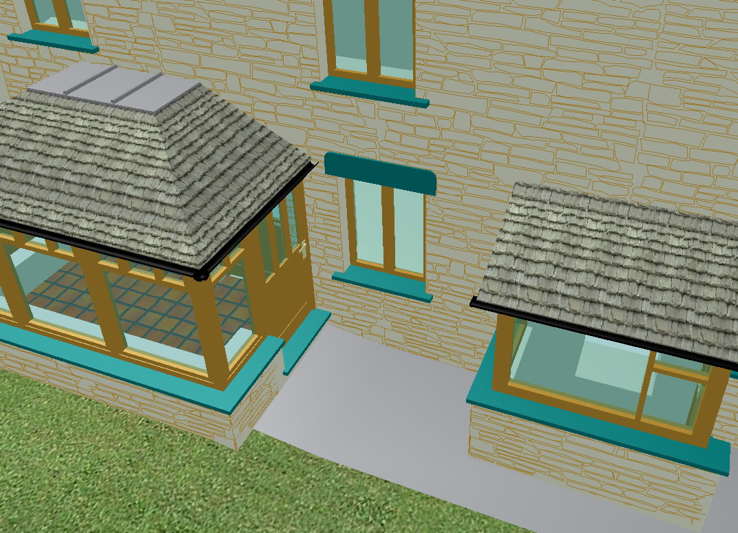
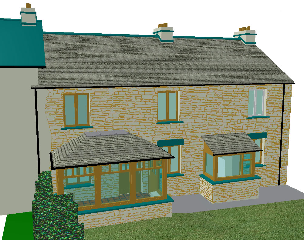
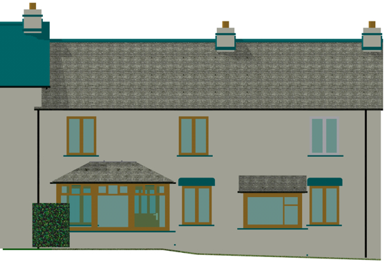
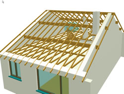
The stonework on these cottage walls is drawn with 3D lines...
apart from a speed advantage over textures the real benefit for me is that they show up in the elevations.
Click for larger image  (263Kb)
Click images for larger versions

Click for larger image (243 Kb)
I created the stonework automatically using the Smart Fit module (as described in my 2D techniques page), exploded the Smart Fit regions into polylines, exploded the polylines into lines, converted them to 3D lines, rotated them 90° into the vertical and moved them just in front of the walls. Thereafter I cut and pasted sections as needed... Not for every job maybe but useful here.
Also, as 3D lines are very thin (how thin?) they disappear when full ray-tracing is used but work OK in 'quick ray-trace' mode and as here in screendumps.
For textures to show up in elevation you can make a render with the
'get image from active viewport' option checked - but I have never managed to get this to render to scale... and it can be unstable.
It does work with Cinema 4D XL ...
as shown (right), but plotting to scale is still a problem.
Click for larger image (132Kb)
Auto-update Smart Symbols...

Watch out for this option which is unticked by default ...

This dialog is available from 'Tools->Options->Architecture'
It is not immediately obvious but I think what it does is make smart symbols designed with the Smart Symbol Designer - i.e. doors and windows - resize to any modification in the window opening size.
I would have thought that this was 'normal' and expected behaviour but for some reason the default is Off.
Modify Smart Symbols...

Update May 2003 Allplan 2003 has new features to help with editing smart symbols.
When choosing the editing option all foils are displayed and the whole process is much more user friendly.
Update Sep 2004 Allplan 2004 takes this a stage further. You can edit smart symbols created with the Smart Symbol Designer tool.

A really useful tip this one [pre v 2003 ]

To modify a smart symbol do the following:
1.Insert the Smart Symbol whose properties you want to change.
2.Menu Tools->Smart Symbols -> Modify smart Symbol
Modify Smart Symbol
3.Click on the smart Symbol's representation whose parameters you want to change. (The Smart Symbol flashes once or sometimes twice).

4.Now use Modify Format Properties Modify Format Properties to change pen (or other attributes - or you can modify, delete or add elements using any tool) of the displayed foil
5.Make the desired changes.
6.Press ESC (you may need to press ESC twice - once to exit the tool in use and once to exit the original command... this is not obvious) and accept the pop-up dialog offer to save (or not) the Smart Symbol.
7.NOTE: you must repeat the procedure for EVERY single foil of the Smart Symbol (for every Reference Scale or 3D View).


Remember to watch the command prompt which asks for input at a couple of places. Also if you save it in the Office symbol folder as I did and then wonder how to load the symbol using 'Get from library' you have to click in the right hand window of the 'Get from Library' dialog - the entry marked 'Tagged Symbol' will take you to your smart symbol directories.

Another tool that does not appear in the actual Smart Symbol Module but does appear in the Tools->Smart Symbols menu is this one
Append Element to Smart Symbol Append Element to Smart Symbol ... which sounds interesting - it seems to allow you to add new elements to an existing foil but according to the online Help these new elements are stretchable unlike a normal smart symbol. (Must check this out in more detail....)
Also...
Smart Symbol Catalog Smart Symbol Catalog does appear in both locations and brings up a file list of 'tagged symbols' - the ones you have saved yourself not the standard Nemetschek ones - for viewing or deletion
Modify Display Parameters Modify Display Parameters appears only in the Smart Symbol module and allows you to add new foils, change the resizing parameters or reference points in an existing smart symbol

Wireframe option in Animation...

Update May 2003 Allplan 2003 has moved the Wireframe option to the toolbar at top or bottom (I put mine to the top) of the actual Animation window. Neat :-)

Sometimes it is useful to use the 'wireframe' option for the animation window - not so much to increase speed (which it does) but more to see relationships of elements. The switch is in 'Tools->Options->Animation' along with the anti-alias option and 'fast or nice' for textures (fast always looks better to me) - you can also click on 'About' for information on your OpenGL driver implementation. Note that the Animation option is only available when the Animation window is active

Allplan 2004
the animation options have moved - right-click in the animation window when active [F4].
standard animation view
with the wireframe option turned on
 
Joining walls... order of overlap?

Join Walls After some trial and error testing it seems to me that walls join in the following order (unless someone knows different!):
illustration of multi-layer walls joining Selecting the horizontal wall first and then the vertical produces this result - with the vertical being lengthened at the expense of the horizontal wall.
illustration of multi-layer walls joining 2 Selecting the vertical wall first and then the horizontal produces this result - with the horizontal being lengthened at the expense of the horizontal wall.

Thus the rule would appear to be that the 2nd wall overlaps the first.

This seems to hold true even on an internal corner
 
Drag and drop imports ...

Only recently has it occurred to me to try 'drag & drop' from Windows Explorer direct into a drawing file in Allplan. As I have accumulated many 3D dxf files from various web resources drag & drop has proved a very useful method for 'checking out' the models.
drag & drop demo As illustrated here I just set up a Windows Explorer window and an Allplan one (set to 'Animation' (F4) view ) - then left-clicked and dragged a filename from Explorer into the Allplan window and released the mouse button... Allplan then automatically imports the model and it appears in animated view. Once I've inspected the model I either click 'Undo' to remove it and then drag & drop the next file in the list from Explorer into Allplan or any that I want to keep I can save as a smart symbol.
If the import does not work you may have to do the first one manually and save the settings because Allplan will use the current settings for the particular file type that you are importing using drag & drop. In particular I would check the dimensions as they are likely to be out by some factor of 10 - this can be changed in the manual import advanced settings.
All extremely clever and it works with 2D drawings just as smoothly.

Update 16.02.02 - Note, do not make my mistake of ticking the 'explode elements' options in the 'Advanced' options for File->Import or the models come in as 3D lines instead of surfaces!
If the models come in at the wrong scale try setting the metres/centimetres etc. option to a different value and then 'Save' at the bottom of the 'Advanced' import dialogue which will then apply these settings to both drag & drop and normal File->Import.

Jump to other Tips & Tricks Pages
Page 1 | Page 2 | Page 3 | Page 4 | Page 5 | Page 7 | Page 8

Top of Page

Home ¦ Park Issues ¦ Services ¦ Local Links ¦ Technical Section
Allplan FT Users Page 1

   
disclaimer - please read!

Site © WSA 2015