William
Sutherland
Architect |
| |
|
|
 |

Click
Here
to Return to
Allplan FT
Users Page 1
Office
Address Cluan
Rydal Road
Ambleside
LA22 9BA
015394 34489
For
location plan
see Local Links
|
 |

|
Tips
& Tricks...
 |

User
Pages for
Allplan FT |
|
| Use
slab tool for curved wall ends... |
|
|
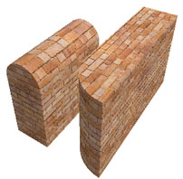
 The Slab tool can be used to create walls
with curved ends - or curved tops. This is because the
The Slab tool can be used to create walls
with curved ends - or curved tops. This is because the  Fillet tool can be used in plan view
on slabs...
Fillet tool can be used in plan view
on slabs...
 |
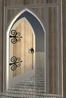
(Left)
slabs in plan view after using Fillet tool to round ends
...(Right) view in animation window with a brick texture also
applied... |
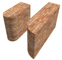 |
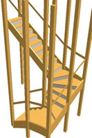
To obtain a round topped wall, use the  Convert Elements tool to change
the Archit. element (the slab) to a 3D (dumb) object. This allows
the wall to be rotated 90 degrees to give the results shown
below.
Convert Elements tool to change
the Archit. element (the slab) to a 3D (dumb) object. This allows
the wall to be rotated 90 degrees to give the results shown
below. |
 |
(Left) slabs in plan view after conversion of top one to dumb
3D object and rotated 90°
(Right) view in animation window... |
 |
If
you wanted to retain wall intelligence then you could further
convert the wall to planes (but turn off any textures or surfaces
applied as I have shown here or you will receive an error message
in German!) using  'Create->Architecture->Architecture->3D
to Planes' and then use the
'Create->Architecture->Architecture->3D
to Planes' and then use the  Freeform Wall tool with the height options set to align
to top and bottom planes.
Freeform Wall tool with the height options set to align
to top and bottom planes.
You could of course have used the
Freeform Wall tool anyway to create
the flat topped wall by making a 2D outline and then filling
it, but using the slab tool method is the simplest way I can
think of making the curved topped wall.
... hmmm, you could probably also
use the barrel vault roof frame tool as well to make the curved
top walll.
|
|
| Use
alternative color palettes... |
|
|
The
default colors are not very subtle and look harsh in the animation
window.
 Use 'Assign Custom Surfaces to 3D/Archit. Elements'
(right click any element) and instead of choosing a surface or importing
a texture file, click on the 'color' option (defaults to white)...
then, change the palette to one of the others provided - my favourite
is Brillux Scala. Now you have a wonderful range of pastel shades
which you can apply and will only show up in the animation window
or in renders. You will need to save the color as a surface when returning
to the original dialog - Allplan will remind you if you forget to
do this. As with texture files you can also click on the 'Details'
button and add reflection and other parameters to the color chosen.
Use 'Assign Custom Surfaces to 3D/Archit. Elements'
(right click any element) and instead of choosing a surface or importing
a texture file, click on the 'color' option (defaults to white)...
then, change the palette to one of the others provided - my favourite
is Brillux Scala. Now you have a wonderful range of pastel shades
which you can apply and will only show up in the animation window
or in renders. You will need to save the color as a surface when returning
to the original dialog - Allplan will remind you if you forget to
do this. As with texture files you can also click on the 'Details'
button and add reflection and other parameters to the color chosen.
The effect
is applied globally to all projects and so you might wish to save
the colors setup here using the 'save to folder' option at the bottom
left of the dialog. |
| No
colour fills in pattern definitions... |
|
|
This has puzzled me for a long time.
Sometimes different pens and colours could be set in Pattern definitions
and sometimes they would only display in the current pen colour (including
any fills).
After a lot of trial and error I have discovered that the critical
button that must be enabled for lines and colours to appear in the
drawing as defined in the Pattern definition editor is the one shown
below in the toolbar.
It is called 'Default Pen and Color for Display
of Pattern on/off'
 |
|
When defining or editing Pattern fills in 'Tools->Defaults->Pattern'
the Online (F1) Help is not context
sensitive.
You need to type in 'Pattern definition', or similar and select
the sub-topic 'Overview' in the Help Index tabbed dialogue that
appears when you press F1 from
within the Pattern editor.
This will give further links for each available tool in the
editor. |
| Select
the link beside the icon for the above tool and it takes you
to some interesting further information including a link to
'Regulations concerning display of elements
on screen' which describes the hierarchy of colour display
properties. |
|
| |
|
As far as I can see Allplan does not have a 'healing' tool to join
lines once they have had a segment deleted - very strange.
Anyway, to get round this I use the 'Lengthen
Lines' tool in 'Edit->More tools'.
 which will extend one 'cut' end to meet another.
 |
|
 |
| Click
on the left line anywhere when prompted for the first position,
then on the end of the segment and finally on the end of the
other line across the gap and Allplan will make the lines meet.
They still will be two separate lines but will look continuous
. |
|
| Section
tool not working? ... |
|
|
I
have been caught out a few times by creating a section line on
plan and when activated find that it either will not work or nothing
is shown in the viewport.
The answer seems to be to check the bottom height of a vertical
section.
The properties seem to remember the last setting and if
set to 10 metres for example will not 'see' your model which may
be at the default level of zero.
A cure is simple enough - after clicking on the section tool, click
on the properties before drawing the line and set the levels to
appropriate values. |
|
|
|
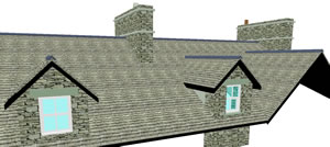
It
does not seem possible to copy a roof dormer. If you try to select
it the whole roof frame is also selected. The only way I have found
of doing this is to use the Plane
to Frame tool.
 I
would recommend making a copy of the roof frame first to another
drawing file just in case it does not work out how you intended
and you can have another try. I have found that this will allow
dormers to be copied in situations like below... where a row of
identical dormers is needed to a roof. I
would recommend making a copy of the roof frame first to another
drawing file just in case it does not work out how you intended
and you can have another try. I have found that this will allow
dormers to be copied in situations like below... where a row of
identical dormers is needed to a roof.
The only strange side-effect of doing this is that when copying the
hole in the roof covering where the dormer occurs, it disables the
option in Roofcovering properties to have the roofcovering omitted
at the
dormer - i.e. the roofcovering aligns itself with the dormer roof instead
of being omitted altogether. A minor nuisance.
Please note that the dormers shown above have the overhanging roofcoverings
created in a different drawing file to the opening for the dormers
- I just copy the roofplanes into several files - one for the walls,
one for the main roofcovering and another for the dormer roof overhangs.
I also tend to make further copies for the rafters, but that is really
just because I seldom use layers.
Update 06.05.2003 - UK technical support say that you should be able
to use the Move Plane tool in the Roof Modeller module - point at the
plane containing your dormer and then you should be able to move the
dormer.
I've not tried this yet.
Update 03.12.2006 - It seems to me when using the Copy Plane tool that it will refuse to drop the copy until you have indicated the number of copies in the dynamic toolbar box - i.e. normally 1, then hit Return to confirm, and then you can place the copy. Very strange behaviour. |
| Change
doorswing direction in plan |
|
|
| No
need to go into Door Properties for an existing door.
Just double click on the doorswing and the doorswing dialog will
appear.
Click the same doorswing again to change orientation or choose another
type.
Very neat.
When we used to draw these on tracing paper, scratching out the doorswing
and redrawing it was a real pain :-) |
| If
all pens in
construction line style |
|
|
|
A
strange but very occasional problem has been reported across
old (v16) and new (v2003) versions of Allplan.
If you suddenly find that all lines are being drawn in construction
line format - even plot layouts - so that nothing will plot and
3D
elements do not display in the animation window, the answer -
and this is the only thing that will cure the problem - is to
click on the drop down list of line styles and reselect a linestyle.
What seems to be happening is that Allplan has no line style,
or possibly pen, selected internally and is drawing everything
in 'no linestyle' - or possibly just alerting you to the problem.
Why it happens is not clear but this is the only way I have
found so far to fix the problem when it happens.
|
| How
to resize plot layout windows |
|
|
|
 Plot
layout Windows are really useful - allowing you to group drawing
files brought into the Layout editor and so move them all around
as one unit on the sheet. Plot
layout Windows are really useful - allowing you to group drawing
files brought into the Layout editor and so move them all around
as one unit on the sheet.
What is not so obvious is how to change the size of the 'window'
on the drawing files included.
The tool required is 'Modify layout window' (fairly obvious!)
and from the offered list of sub-commands choose 'Scale
Layout Window'.
Then indicate a corner of the layout window you wish to resize
and Allplan will immediately give a 'rubber band' on the corner
allowing you to drag the window size in and out. Place a point
for the corner and repeat as often as necessary.
|
| [v2003]
Circle will not rubber band.. |
|
|
|
Allplan
v2003 introduced many helpful touches - one of them seems to
be remembering the last input value.
When you select the circle
command it is now common to find that a value already exists
for radius in the command line box entry. This has the slightly
unfortunate effect of making the circle radius jump to that value
and although it can be overriden by snapping a point, to have
the 'rubber band'-ing of radius available as it used to be in
previous versions, you need to change the input value to zero from
whatever was already there.
|
| Window
head ignores top of opening |
|
|
|
I had a problem recently where the top of the window created in
the Smart Symbol Designer would not align itself with the top of
the window opening in a wall.
The solution was to set the lintol height to zero in the Reveal
settings in the Window Properties.
No idea why this works but lintols are probably best omitted from
anything other than very standard types of walls. |
| No
filter on imported circles... |
|
|
|
After importing a dwg file if you find that circles and other elements
cannot be selected by the filters in Allplan, right-click on a circle
and check if the line, colour or pen is assigned to 'From
Layer'. While you can then press the Layer button in the
dialog to individually switch this off by unticking the check boxes
in the Layer dialog, it is best to use the Option button when importing
to check the box in the bottom right of the Advanced Import Options->Explode 'From Layer'. This removes this feature from the elements when imported. |
| Pantone & RAL colour Palettes ... |
|
|
|
Although listed in the standard Allplan colour library RAL is not included - a pop-up says a licence is needed. Well, at the moment [August 2005] it is possible to download the RAL, and also the Pantone colour libraries from the wonderful resources page at Nemetschek Hungary. (Note..Internet Explorer ONLY)
(Under the Button LETOLTESEK/KIEGESZITOK)
Just download and double click the self-extracting files - the default location is c:\Allplan\2003\.... Then navigate in Windows Explorer to that folder and find the Setup file which will install the colour library in Allplan.
Then you can find RAL listed - with a list of plotters to choose from for colour matching.
The Pantone library is installed under the 'Custom RGB' heading in the drop down list of colour libraries in Allplan (available when using the Paint or any colour commands).
Wonderful :-)
 < Click for larger image < Click for larger image
Note some of the other downloads on nemetschek.hu - the Velux installer looks very interesting - it is a much requested feature in the UK.
|
| Roof Plane Levels wrong... |
|
|
|
If you find that a Roof Plane Properties dialog shows correct bottom level but walls or other objects being controlled by the roof plane seem to ignore this setting - typically when you have a dormer on a roofplane - try using 'Move Plane' from the Roof Modeller tools to individually move parts of the roof (make a marker so that you can put the plane back afterwards) then individually change the bottom level and then back again using the Properties dialog. Altering each plane on its own should correct the problem.
Note that if you change one Roof Plane when there are several planes working together - as in a dormer situation for example, then Allplan seems to default the bottom level of All Roofplanes to the lowest level of any plane in the combination - this is normally visible in the Isometric view window. |
|
|
|
|
Here is a neat feature I did not realise existed.
If you create a Saved view using the icon on the viewport toolbar...
When you Load the view - or just double click the saved name in the list...
then as long as the icon in the viewport toolbar remain active, double-clicking the middle mouse button or Keying F5 will always zoom the screen view to this saved view.
Very nice :-)
|
| Keep text visible at all zooms... |
|
|
|
Here is a neat tip from UK tech support...
To keep text visible at all zoom levels - i.e. so that it does not become just a box when you zoom out - click Tools->Options->Text and set the option 'Text legibility threshold' to 0 (Default is 1).
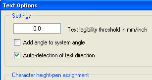
On larger monitors particularly this is a great help.
|
| stretch /extend section lines... |
|
|
In Allplan 2004 if you wish to stretch or extend a section line you must have created the section line with the option box ticked that says ' Show interactive solids (as construction lines)'.
You find this option by clicking the Options button on the dynamic toolbar whichh appears onscreen after clicking the Define Section tool. It is on the right side of the dialog that appears.
|
| if bitmap fills will not plot ! ... |
|
|
In Allplan 2004 onwards - for some daft reason, Bitmap areas seems to be turned OFF by default in Plot elements / options - it is the first dialogue you are presented with when you click 'plot' - in the right-hand pane.
Just enable this by clicking the option to highlight it and then bitmaps should plot OK. If having trouble with transparency try the advanced option in plotter preferences to set plotter driver to 'avoid out of memory errors' - in earlier HP drivers this used to be called something like 'do plotting in PC' - it means the same thing - the PC does the rasterising (turning into dots) of the image rather than the plotter so that it does not run out of memory.
|
| Animation window screenshots ... |
|
|
It has been a while since I did any 3D work in Allplan since v2003 and I notice some nice enhancements to the animation window in v2004. This may have been possible before and I just did not notice...
Maximise the animation window, set up your view the way you would like it and then just click the button on the window toolbar (bottom right by default) 'Copy to Clipboard'.
Open Photoshop or any similar application, click File->New to create an empty new document and then just Ctrl+V or Edit->Paste and the screenshot will appear in Photoshop or other application for editing/printing.
I use this sort of technique for client presentations at the design stage - very quick and can be plotted quite large.
|
| Save Animation window views... |
|
|
A tip from CAD Ltd ...
There does not seem to be a way to save a view set up in the animation window in Allplan 2004. However a quick workaround is to use an isometric (i.e. 'normal' 2D view) view window... click on the '3D view' icon on it's window toolbar (the icon looks a bit like an envelope).. when the dialogue box pops up use the double chevron arrow button... clicking it will make the dialouge disappear temporarily.. just click in the animation window and then when the dialouge box reappears click 'OK'. Now your isometric view matches the animation window view and this can be Saved using the next folder icon on the toolbar. To reinstate an Animation Window view, just do the reverse.
Very neat.
|
Top of Page
Home
¦ Park
Issues ¦ Services ¦ Local
Links ¦ Technical Section
Allplan FT Users Page 1
|
 a
pale gold color
a
pale gold color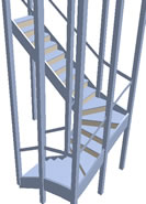 a
more bluish color
a
more bluish color